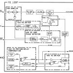
With the lab power supply, the YTO worked fine, so I did some further investigations on the 8341A’s YO loop…
UPDATE: power flatness test!
To protect the YTO from further stress, I decided to completely remove it.
Then, I measured the voltage from the PRETUNE DAC. This voltage is converted to a current which then drives the YO’s coil. There are 4 frequency bands:
Band #0 from 0.01 to 2.3 GHz
Band #1 from 2.3 to 7 GHz
Band #2 from 7 GHz to 13.5 GHz
Band #3 from 13.5 to 20 GHz
Then I put the instrument in CW mode and measured the output voltage called VDAC.
When the knob is rotated, VDAC increases linearly, until a bandcrossing is reached, where it suddenly drops back to 0 volts. This behavious seems good to me, so no problem with the DAC.
Next, I measured the PRETUNE voltage. According to the service manual, it should have a value of -2.5V/GHz. In CW mode, I entered following frequencies and measured the voltages indicated:
| 10 MHz | -9.72 V |
| 1.01 GHz | -11.76 V |
| 2.01 GHz | -14.25 V |
| BANDCROSSING! | |
| 3.01 GHz | -7.52 V |
| 4.01 GHz | -10.01 V |
This looks good; I cannot really verify whether the absolute voltages in band #0 are correct, but in band #1 it looks very nice. The difference between two adjacent frequencies is always 1 GHz, and thus, the voltage difference is also always -2.5 volts. So, the pretune voltage is fine!
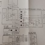
If the pretune voltage is fine, the service manual sugests to troubleshoot the sense resistor assembly…
… which consists of several power resistors and a power transistor mounted to a heat sink. Haha, what should go wrong here?! just to be sure, I checked the power transistor with a diode tester. No problem here, looks fine.
Next, I connected an external 100 Ohm power resistor instead of theYO coil and measured the current through the resistor while the instrument was still in CW mode. I measured following currents through the resistor:
| 4 GHz | 92.8 mA |
| 5 GHz | 116.4 mA |
yup, that looks good, since the service manual shows that there should be a current of 24 mA/GHz. So the YO coil driver is fine as well!
Then I decided to give it again a try with the YTO. Installed the YTO and measured its coil voltage… still 40 V! and no sweep and no power output from the YTO. Something is strange….
Tested theYTO again with the lab power supply and the spectrum analyzer. No problem here, it oscillates!
Next, I decided to measure again the coil resistance of the YTO. 50 ohms as previously, this looks good to me. Just for fun I measured the resistance between the main coil and the housing….. and HA! there was 51 ohms on one end (pin 10) and 1 ohm on the other end (pin 9). According to the schematic, however, there should be absolutely *no* connection to the housing! because the housing is grounded…
I then decided to remove the YO Bias Board and checked again the resistance to ground. There was still a short circuit. Okay, apparently, I must open the YTO and see whether something can be done…
Hmm, this looks like there is no serviceable parts inside, and I am afraid of opening this construction because I am unsure whether it will be possible to put it back together afterwards.
The problem with this short is: pin 10 is tied to -40 V. If pin 9 is shorted to ground, the YTO sees the full 40 V across its main coil, regardless of what the YO current controller does. So, the YTO is heavily detuned – probably the reason why it didn’t work.
But from a friend, I heard following story: he had an audio amplifier using germanium transistors. And suddenly, these transistors had a short inside them. He said the reason was that there was some whisker inside the transistor which made a contact to the case. He was able to fix the transistors by discharging some large electrolytic caps through the whiskers 🙂 Probably I have such a whisker in my YTO as well? Since the YTO is completely useless in this condition, I decided to do the following:
I grabbed a strong lab power supply and hooked up the shorted pin and the case of the YTO to it. Then I cranked up the current. At 1.5A, something inside the YTO zapped, because current suddeny dropped! there was still about 1 or 2 mA or so, but much better than before. To verify that I have not damaged anything, I checked the coil resistance. Still 50 ohms, so the coil is fine. The YTO also still works when connected to the spectrum analyzer and lab power supply. YEAH!
The resistance between pin 9 and the housing is now about 20 kOhm. Not yet very good, but better than before.
With yhe YTO back in the instrument, phase lock is achieved, but only sometimes. I guess that the 20 kOhm generates an error current which disturbs the PLL, somehow…. I got no spectrum analyzer picture from this, but it looked really ugly. The YTO was bouncing around quite crazy. However, when I used the lab power supplies to operate the YTO, it worked fine. The power supplies are galvanically isolated from each other, but in the 8341A they are not, so, if there is a short inside the YTO, this will not work. I tried the same procedure of ‘burning’ the whisker (or dirt) away again, but this time, I was unlucky: resistance dropped to about 1 Ohm and stayed there.
Since the instrument cannot function properly with this YTO, it can be considered damaged, and there is no possibility of fixing things, so I decided to open the YTO to see whether there is a possibility to fix it.
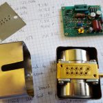
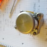
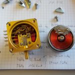
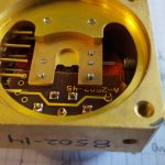
Removed the 8 screws which hold that thing together. As soon as I had it open, a funny smell came to my nose. It smelled like burnt electronics  🙄 No surprise since I fired more than 1 Amp through some sort of dirt to ‘burn’ it away. This is how the YTO looks inside:
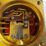
with top coil removed:
As one can see, the top most feedthrough capacitor is black and burnt. But more on this later. First we have a look on the other side!
With bottom coil removed:
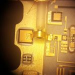
Unfortunately, I don’t have one of these fancy microscopes with USB camera output, so I used my phone’s camera to take some photographs from the microscope, which worked quite fine 🙂
This is a picture of the YIG sphere with its coupling loop. The sphere is smaller than 1mm.
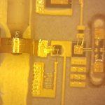
The hybrid circuit is connected to the feedthrough capacitors by means of bond wires, as one can see here:
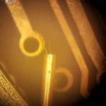
This is a picture of the heavily burnt feedthrough capacitor:
First, I checked the two coils. None of them has a short to the housing, which is good news. This means the coils are definitely O.K.! The short must be inside this feedhtrough capacitor. And indeed, with both coils disconnected, I could still measure approx. 1 Ohm to the case. The small PCB looks fine, so there must definitely be some trouble with that cap.
I thought of cleaning the cap (how could one do that?), or removing it (drilling? milling?) or drilling an additional hole and insert a further cap. All of these solutions are crap because chances to destroy the in principle working YTO are high. But then I was really really lucky: there are in total 10 feedthrough capacitors on this unit, one for each of these signals:
+20V
-10V
-10V filtered
+5V
FM coil +
FM coil-
main coil+
main coil-
GND of the internal hybrid circuit
Did you count? 🙂 this is only 9 signals. And indeed, one of the feedthrough caps was not used, I checked with the microscope and there was NO bond wire attached to pin 6! This means I could retrofit pin 6 with a piece of wire to be the substitute for pin 9. And this is exactly what I did! In the old days, at my company, we could bond, but no longer these days, so I decided to solder a thin wire to the pin.
Of course, the bond wires to the bad feedthrough cap need to be removed. Further, the connector for pin 9 has to be removed on the bias board A44 as well. Instead, I connected a small wire from the appropriate signal to the pin 6, which is the new main coil connection.
Just to be sure, I also cut off the bad feedhtrough cap’s pin on the outside and mounted everything back together.
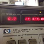
Put the YTO back in the instrumend and turned power on… the first sign was really promising: the ‘UNLEVELED’ annunciator is off and apparently, I have now a 0 dBm signal at the RF output 🙂
Further, the ‘UNLK’ annunciator is gone as well!
However, the green YTO lock LED inside the instrument was still flashing sometimes. So I did the adjustment procedure as described in the service manual and now the YTO locked LED stays on all the time! YES! 😎
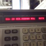
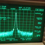
The signal output in CW mode is really nice:
It seems like the problem is fixed! Just to be sure I measured the voltage across the main coil. It was around 6 V, which looks good to me. Not 40 V as before.
Now I have a last thing to do: The RF output connector is on the instrument’s rear panel. This is unhandy. But apparently, there was a retrofit kit from HP to move the connector to the front, which is of course no longer available. Luckily enough, my instrument seems to be ready for a front panel N connector:
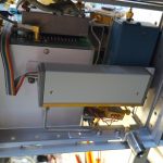
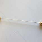
I removed the cover and dismantled the front panel so I could get access to the innards of the instrument. Next, I removed the semirigid coax cable which connects the attenuator (which is right behind the front panel) with the rear panel’s RF output. To remove the coax cable was quite a PITA because it is really complex bent around different corners and assemblies. This is the removed semirigid cable:
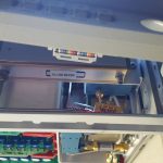
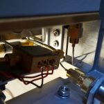
This is the attenuator behind the front panel, where the RF comes out:
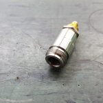
The removed output connector:
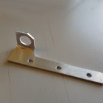
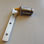
I grabbed a piece of aluminum sheet metal and manufactured a bracket which can be installed on the instrument’s front frame using screws. This is my bracket:
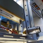
As described before, I mounted the bracket with the connector on it at the instrument’s front frame. This is how it looks:
I then made my own semirigid coaxial cable assembly 🙂
This is the attenuator connected to the N connector mounted on the bracket, using my semirigid cable from above:
It looks quite genuine as soon as the front panel is put back on!
After a bit of cleaning works and putting the covers back on the instrument, it looks like brand new and it even has front panel RF output 😎
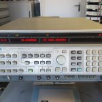
My next project on this machine will be to do the performance tests and do some calibration. But so far, the power flatness seems to be quite good and frequency stability is also really fine. My 5316A counter told me that there was a frequency deviation of about 2..3 Hz which I calibrated away by adjusting the ovenized crystal oscillator.
Update: I wrote a small Python program to test the power flatness of the instrument. For this purpose, I used a 436A power meter with a 8481A power sensor. This power sensor works officially only up to 18 GHz, but we can give it a try though 🙂
The Python program uses a Prologix GPIB/USB adaptor. It programs the 8341A to several CW frequencies, then triggers the power meter and waits until the power meter has settled and the meter reading is available. Then the next frequency is programmed. Frequencies and measured power are written to a protocol file.
The Python program uses the command ‘CW’ to set the 8341A to the desired frequency; the syntax is: ‘CW1000000000HZ’ to set 1 GHz CW frequency. The power can be set with ‘PL-10DB’, which sets for -10 dBm output power.
The 436A power meter is queried with the ‘9D+T’ command. This rather strange command does the following: 9 means auto range; D means dBm output format; T means auto trigger. The meter then sends the measurement data as soon as the sensor is settled to approx. 1%.
The power meter responds with a string of the format ‘PKD-0010E-02’. P means: the measurement is valid; K is the auto range sensitivity; D is the unit (dBm) and the number is the actual meter reading.
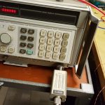
To test both, the ALC as well as the attenuator, I used several settings for the power level: 0 dBm, -5 dBm, -10 dBm and -20 dBm. The power sensor is directly connected to the signal generator’s output:
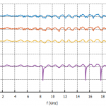
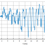
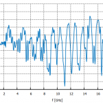
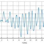
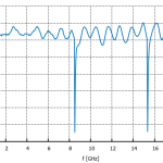
The measured output power is shown in the following chart. The chart shows the actually measured output power vs. frequency, with the requested output power (ALC setpoint) as parameter.
As one can see, there is some ripple in the output power…. The significant dips for the -20 dBm output power are due to insufficient power meter settling time; when I measured the output power at these frequencies manually, the dip was not there.
This is the 0 dBm output power:
-5 dBm output power:
-10 dBm output power:
-20 dBm output power:
These measurements are all done with a cal factor of 100%, which is of course not quite correct, I will implement an auto-correction routine in my program later.

Awesome work! Tobias.
The rear panel output is good if you are to drive a 8510C VNA’s test set. I have to re-route the output of my 83592B to the back otherwise it’s a PITA:)
Great job!
Calvin