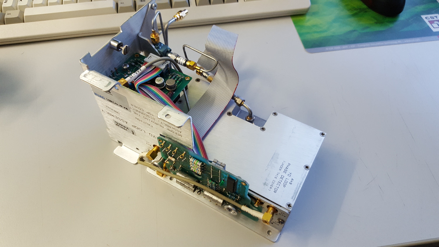
Today, I decided to dismantle the YO loop of my HP 8341A to further search for the problem.
This is the YO loop assembly. The colourful cable is the YTO interconnect cable.
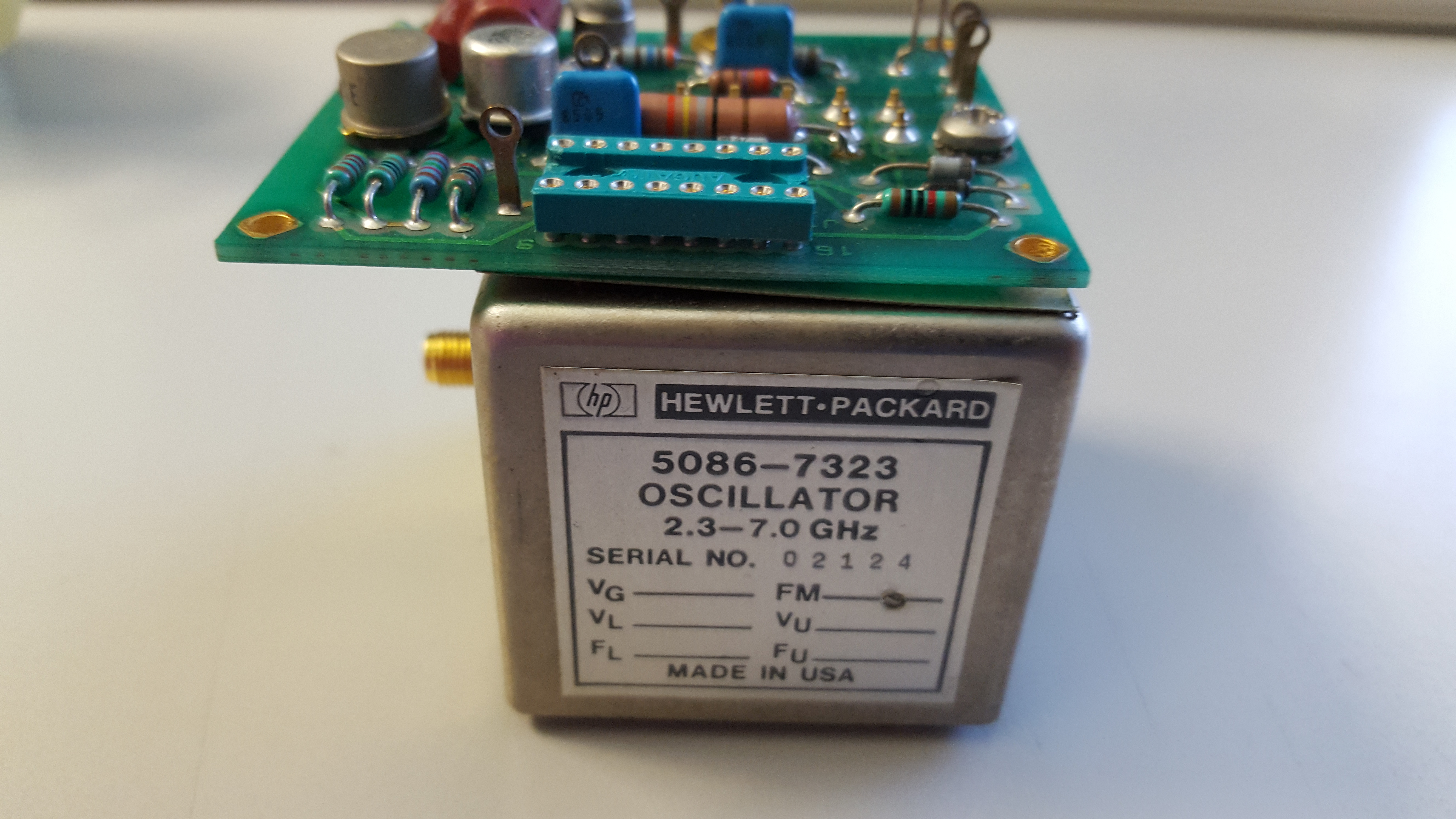
This is the YTO itself with the A44 Bias Board on top of it:
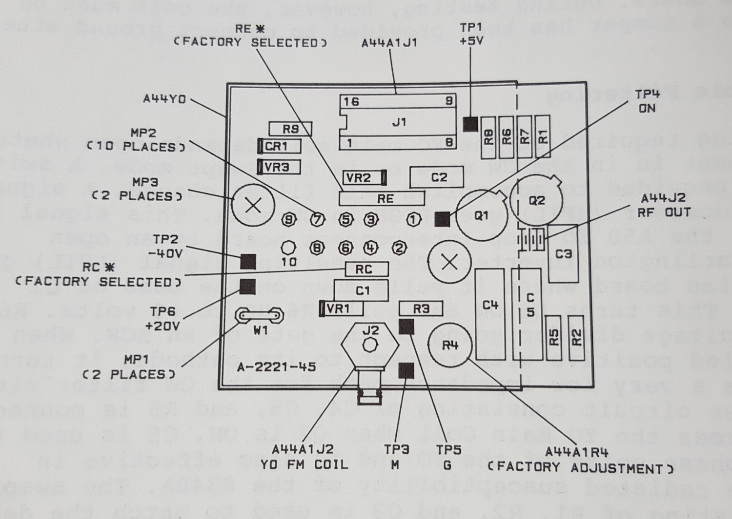
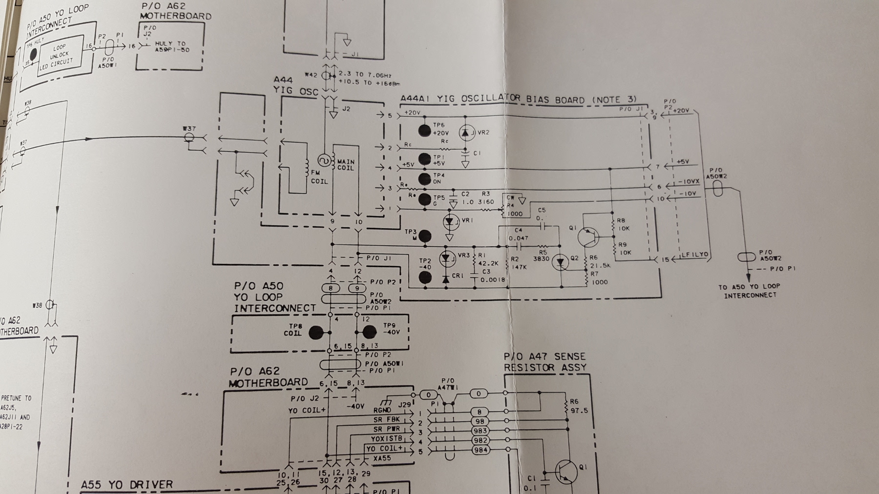
After a bit of searching in the service manual, there is even some schematics of the bias board. It looks like its purpose is mainly to protect the YTO and stabilise and filter some voltages:
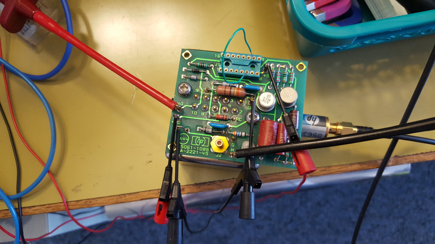
Since I already thought the YTO is damaged, I decided to test it using some lab power supplies. If it works, it’s fine, if it is already damaged, I don’t lose anything. So I hooked up some test cables to it and used different power supplies for the +5V, +20V and -10V. A 10dB attenuator is installed at the output, which then is connected to a 8563E spectrum analyser with additional 10dB of input attenuation.
Apparently, the main coil is connected to pins 9 and 10 of the bias board. I measured 50 Ohms, which looks good to me. So, at least, no broken main coil. This is my test setup for the YTO test:
First, I turned on the +5V, +20V and -10V power supplies with current limit set to a few mA. Nothing could be seen on the spectrum analyser. I then slowly increased (actually decreased….) the voltage on the -40V input. At approx. -1V, with 25mA of current, the SA suddenly showed some peaks! The first peak appeared at 1.95GHz with an amplitude of 5dBm. Wow! I then increased the voltage (and thus the main coil current). At approx. 50mA, the SA shows this:
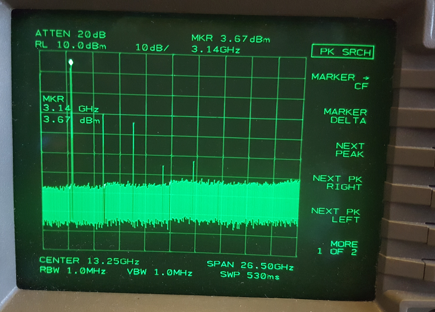
Apparently, no problem with the YTO! I further increased the voltage and monitored the SA.
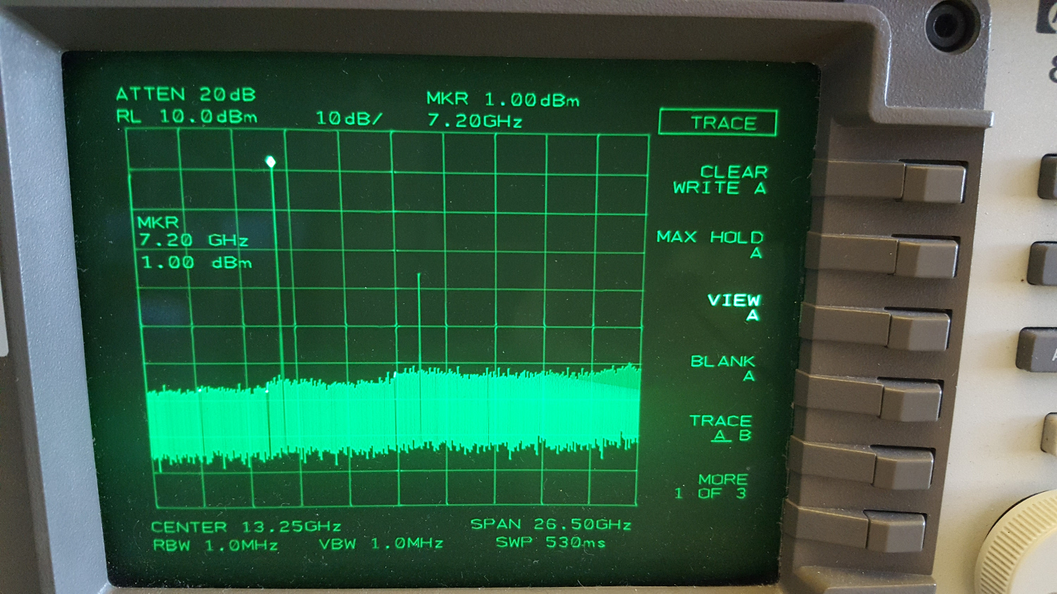
This is at a main coil current of approx. 175mA. Not bad! so, the YTO is not broken, as one might think according to the sticker on the YO loop. It is definitely working and tunable from 2 GHz zo 7 GHz, as it should be. Tuning sensitivity is approx. 32 MHz/mA.
So, next, I will check the A55 YO Driver board, because if the YTO has the proper voltages and current, it should work! I did the following test: I installed the YTO back in the 8341A and connected everything except the YTO’s output . It was connected to the SA. The idea behind this was that I should see something useful on the spectrum analyzer if the YTO is properly working. But in my 8341A, it’s definitely not, and thus, the problem must lie near A55 or behind!
Just for fun I measured the tuning curve of the YTO. A HP 3616A power supply was used as current source for the main coil and the frequency was read from the spectrum analyzer. This is the resulting curve:
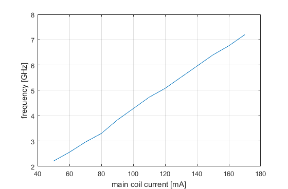
So it is indeed very nice and linear.
Btw, I have attached some interesting documents about YTOs which I found on the net.
