An interesting question made me think about whether it was possible to use lumped element quarter-wave transformers for a lumped element Wilkinson splitter.
In an earlier post, I showed some lumped element quarter-wave transformers. They can be used for matching loads of different impedances.
Well, the Wilkinson splitter also consists of two quarter-wave transformers. For a \(50\,\Omega\) System, they need to have an impedance of \(70.7\,\Omega\). The transmission lines can be replaced by CLC arrangements, with
\(C = \frac{1}{2\,\pi\,f_m\,Z_0}\)and
\(L = \frac{Z_0}{2\,\pi\,f_m}\). Of course it is again possible to cascade several such transformers.
For example, a Wilkinson for 10MHz would consist of C=225pF and L=1.125uH, as shown below:
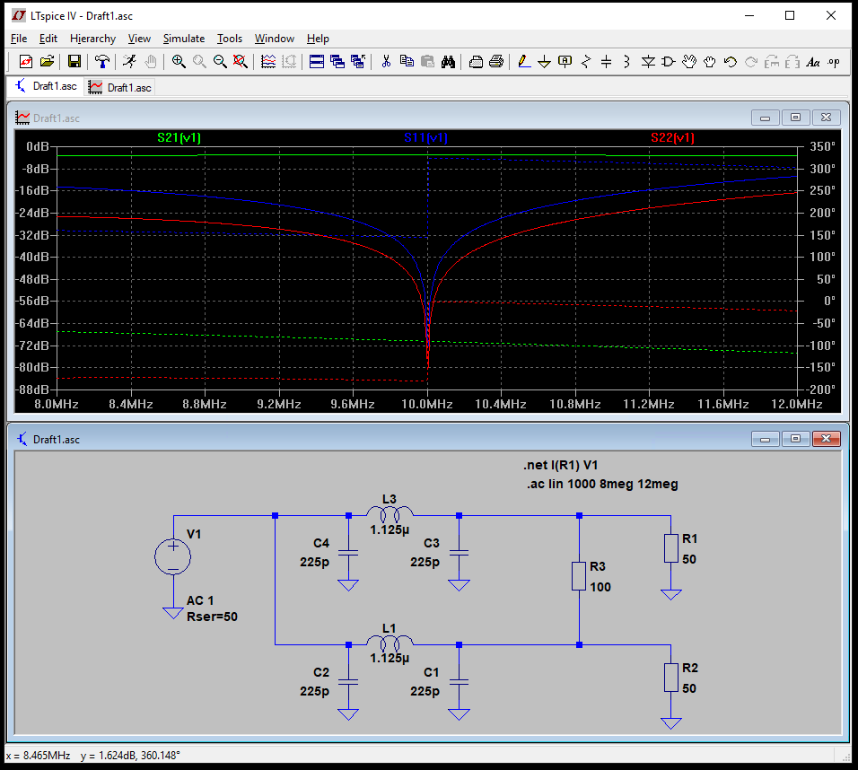
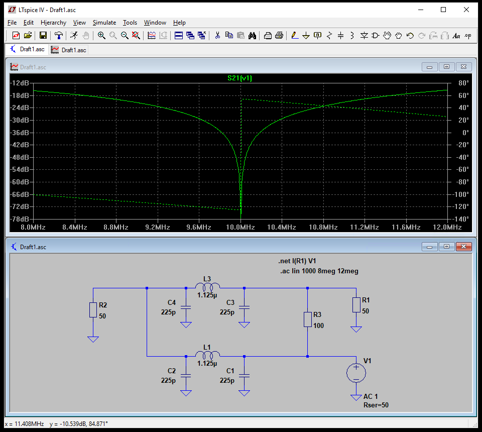
The isolation is quite good, around -70dB, and the insertion loss to both legs is exactly 3.01dB.
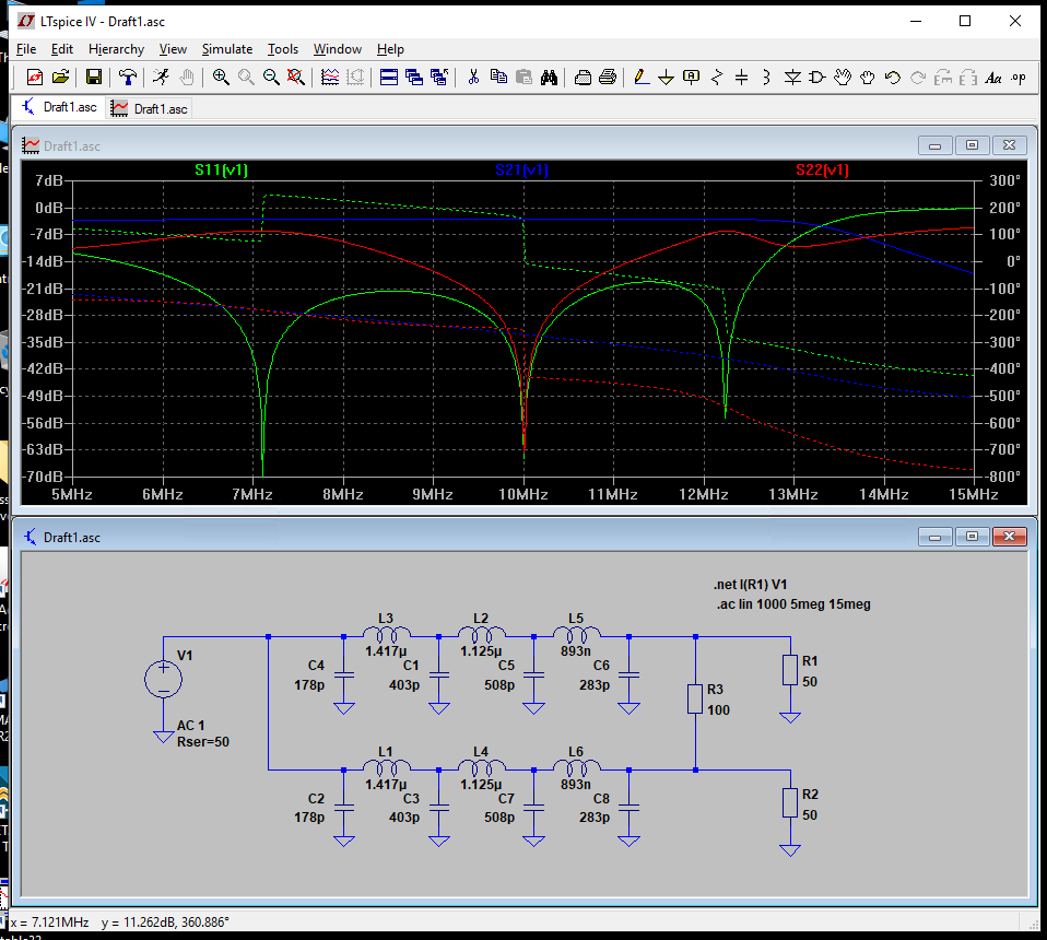
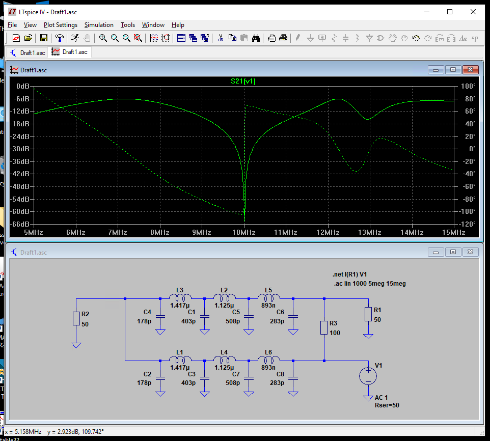
When the quarter-wave transformers are split into multiple stages, the bandwidth can be increased slightly, however, the isolation does not improve much.
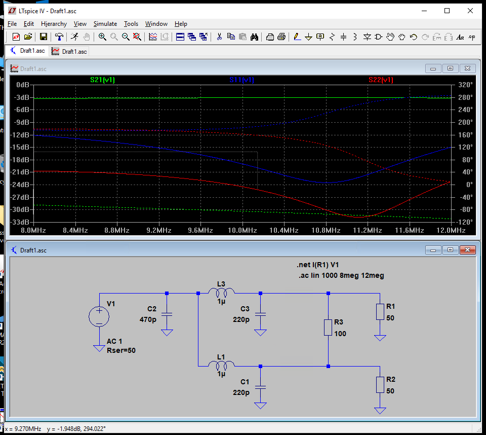
When real element values are used, the input matching degrades to approx. -21dB and the isolation to around 30dB.