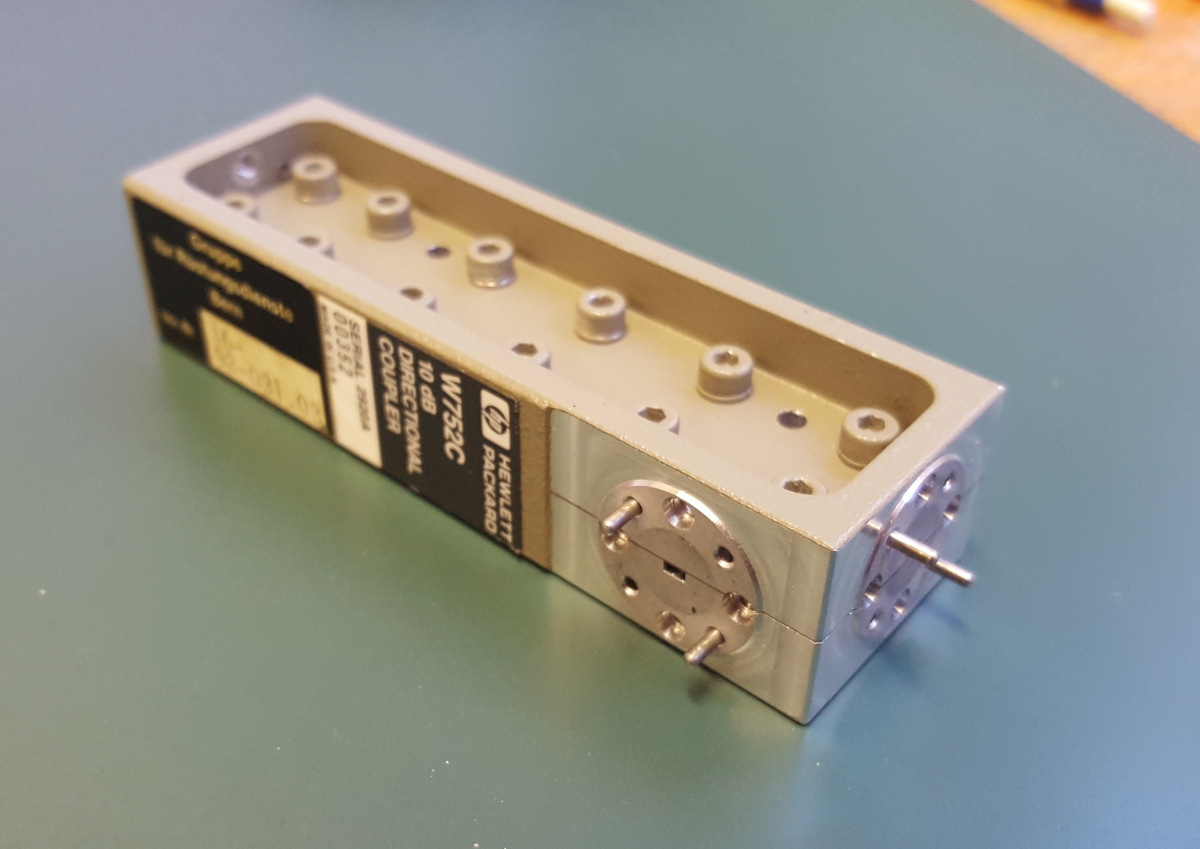
After I decided to make a waveguide coupler to see what results I may achieve, I have disassembled one and looked at its construction. Then I made my own coupler.
My construction will be inspired by this HP design:
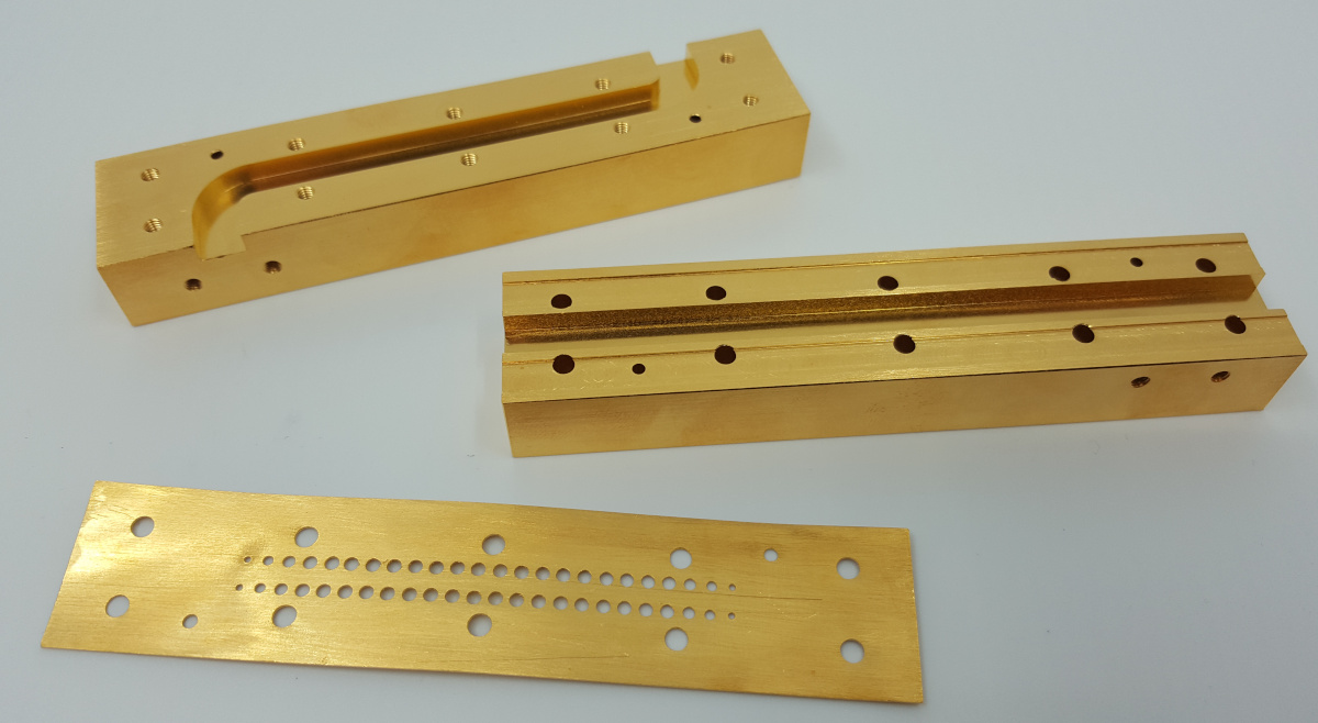
First, I wrote a Matlab script to calculate the positions and the diameters of the holes. After that, I milled the parts on a Spinner VC1020 CNC milling machine – the only one I have been able to learn how to program, so far. The septum with the holes was made by hand. This are the finished parts of my directional coupler:
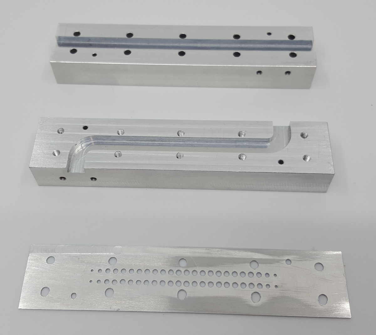
Note the S-curved waveguide which forms the coupled ports. I didn’t want to make a integrated load as well, so I decided to make a dual directional coupler. A load can be connected externally if one wishes to convert it to an ordinary directional coupler.
The septum uses five Chebyshev arrays of 8 holes each in two rows, which yields 24 holes per row. The hole diameters are calculated with my Matlab script (more on that later) and then rounded to 0.1mm.
| Hole # | exact Diameter (mm) | rounded Diameter (mm) |
| 1 | 1.048 | 1 |
| 2 | 1.483 | 1.5 |
| 3 | 1.816 | 1.8 |
| 4 | 1.996 | 2 |
| 5 | 2.019 | 2 |
| 6 | 1.966 | 2 |
| 7 | 1.966 | 2 |
| 8 | 2.019 | 2 |
| 9 | 2.019 | 2 |
| 10 | 1.966 | 2 |
| 11 | 1.966 | 2 |
| 12 | 2.019 | 2 |
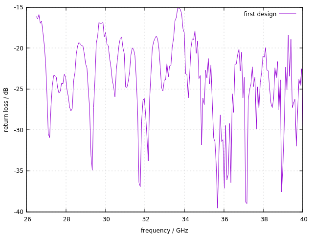
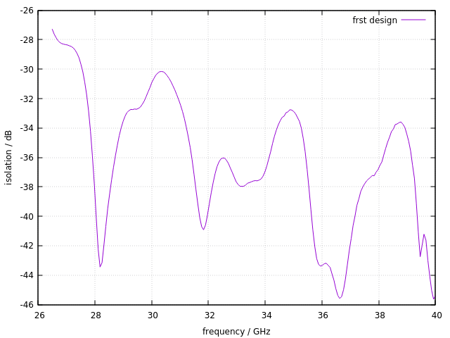
I measured the insertion loss, return loss, coupling and isolation with a R&S ZVA40.
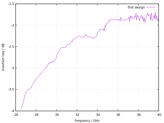
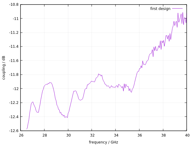
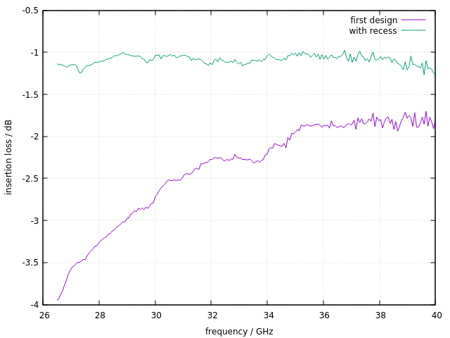
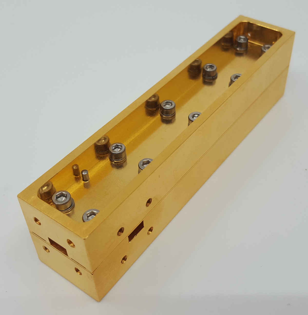
The insertion loss is – more than 4dB at the worst point. The coupling flatness is also not especially good. So I have modified one of the two waveguide parts and milled a small recess to maximise the pressure close to the waveguide walls:
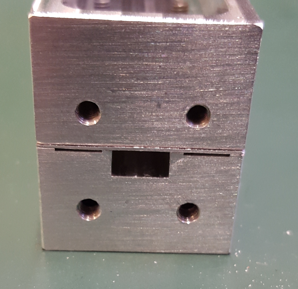
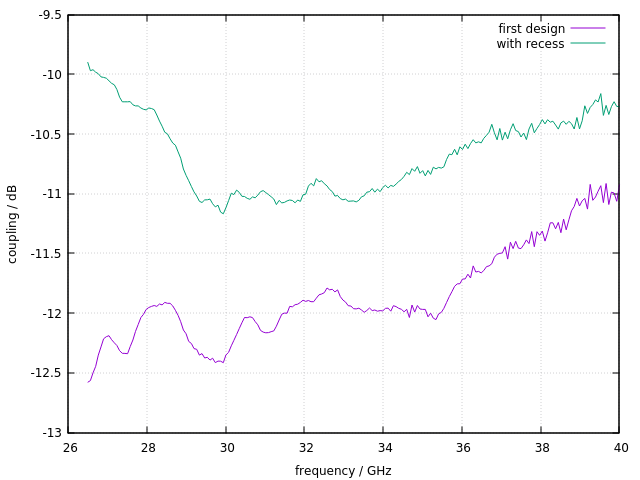
Without the recess, the pressure is quite low because the force from tightening the screws is distributed over a large area. The recess concentrates the force to a smaller area close to the waveguide walls. The impact of this small recess is dramatic:

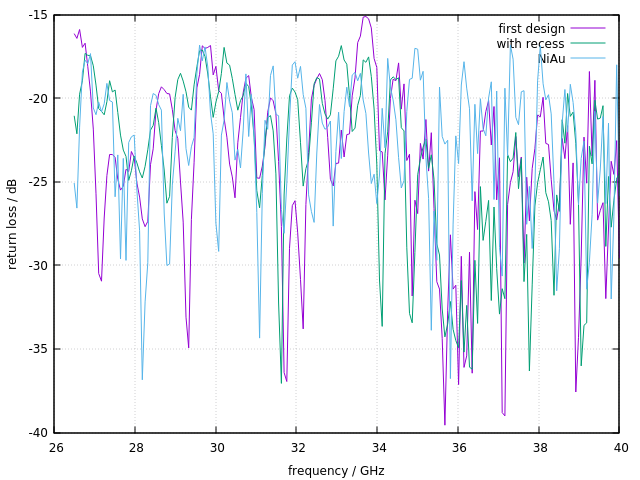
While the return loss is more or less unaffected from the recess (this is perhaps because it is dominated by the return loss of the waveguide to coax transitions I used to connect the coupler to the ZVA40), the coupling is now excellent. A typical commercial waveguide directional coupler from, say Pasternack, has a coupling accuracy of +/-0.8dB – this goal is easily met by my coupler.
The biggest improvement occurs for the insertion loss. The insertion loss is between -1dB and perhaps -1.5dB. Note that this is a 10dB directional coupler, which means that 10% of the signal from the input port go to the coupler port, and 90% of the signal leave the coupler at the through port. 90% power in dB equals -0.456dB, so this means, that a 10dB directional coupler has at least an inherent insertion loss of -0.457dB. This means that my coupler is only 0.55dB worse than that! I cross-checked with a commercial coupler, and there, the insertion loss is also specified with 1dB typical.
The isolation improved as well, but is still a bit disapointing. The worst isolation is -35dB, which yields to a minimum directivity of -25dB. (Note that the directivity is actually calculated with
\( D = S_{31} + S_{21} – S_{32} \)but since the insertion loss is small, the directivity is basically the difference between coupling and isolation.)

Since most commercial couplers available are gold plated, I tried that as well, since I hoped it will improve my coupler even more. Here’s the result:
The insertion loss and return loss did not change much:
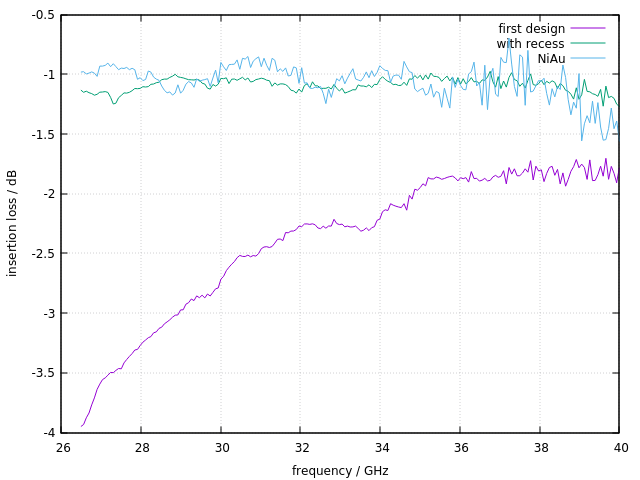
Interestingly, the coupling became even a bit worse. I am not sure whether this is actually due to the gold plating, or whether there is insufficient contact between the top part and the bottom part.

The isolation became a bit worse as well:
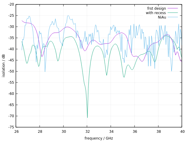
At the moment I have no idea why the coupler’s performance became worse after gold plating. Actually, the gold should have an even better conductivity than alluminium (45Ms/m vs. 38MS/m), but it cannot be directly plated on aluminium. Instead, an additional layer of nickel is made first, and the nickel will introduce some magnetic losses. However, the gold plating is 3..5um thick, while the skin depth in gold at this frequency is around 460nm – so over 99% of the current will flow only through the gold, and the field within the waveguide should therefore be unable to “see” the nickel.
Comparison with a commercial directional coupler: concerning coupling flatness and insertion loss, my coupler is absolutely comparable to commercial couplers e.g. from Flann Microwave or Pasternack. The only difference is in the directivity – this, as my very first design, offers only approx. 25dB of directivity, which is a bit disappointing. According to Flann Microwave, this is called “systems grade”. The “metrology grade” couplers need to have about 50dB of directivity. Since the directivity is mainly affected by the load and the construction of the septum, I will concentrate on these two topics next.
More on the waveguide directional coupler soon! I will try to make a coupler also for Q and U band (33GHz to 50GHz and 40GHz to 60GHz). This should still be mechanically feasible. W band (75GHz to 110GHz) will become interesting, though – its inside dimensions are 2.54mm x 1.27mm only.
To do:
- build a new coupler having an internal termination
- improve directivity
- try to make a coupler for W band
