I have not posted for a long time! Not only because I was too busy in the meantime, but also because I was working on a quite involved project: a new GPSDO!
This is the device I built:
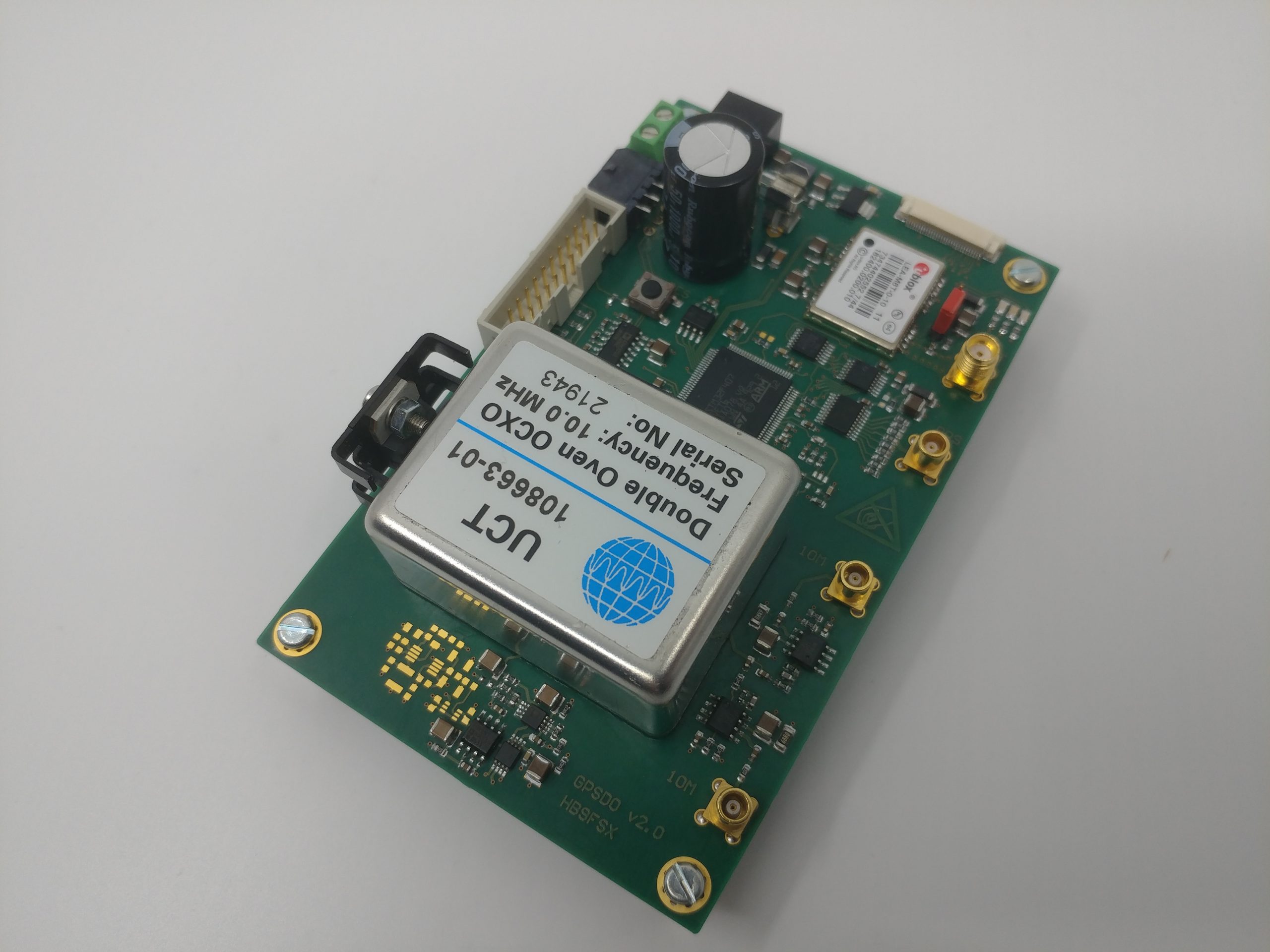
It uses the UCT-108663 ovenized oscillator, which is said to be very similar to the famous Oscilloquartz 8663. In my first experiments, I used a frequency locked loop and therefore the phase was quite arbitrary and the stability was insufficient. This time, I implemented a proper PLL which measures the time interval between the 1PPS pulse from the GPS module and the self-generated 1PPS pulse. The time interval is taken as error signal for a PI controller, which adjusts the EFC voltage of the oscillator.
Controller time constants are changed automatically.
With a quite early development version of the firmware, I made a time-lapse video of the signals on my oscilloscope. The camera takes 1 picture every 2 seconds. The green signal is the 1PPS generated from my GPSDO, the yellow signal is the 1PPS signal from the GPS module, and the red signal is the 10MHz output from my GPSDO. For reference, my Oscilloquartz STAR4+ GPSDO is connected to the blue channel.
This video was taken at an early development stage, so controller time constants were for sure not optimal. But it is still interesting to see how the GPS 1PPS signal jitters quite badly!
TIC measurements
A TIC (time interval counter) is used to measure the error signal for the PLL. The TIC is absed on the TDC7200 chip from Texas Instruments and measures the time interval with a resolution of approx. 50 to 60ps. What the TIC actually measures is the time interval between the leading edges of the 1PPS signal from the GPS module and the 1PPS signal derived from the OCXO. Therefore it measures the phase difference between the two signals and a PLL can be used to control the OCXO.
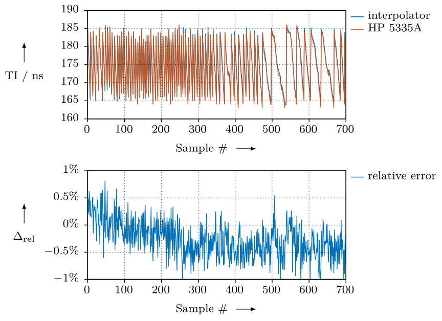
I verified the proper operation of my own TIC as follows: I printed the measured time intervals via RS-232 on the PC. Also, I connected the START and STOP signals to my HP 5335A counter and recorded the TIC readings as well.
Shown below is a plot which compares the readings of my own TIC with the HP 5335A as well as the relative error.
Logged data
Shown below is a plot of data logged for approx. 1 hour. The x-axis are seconds. In the DAC signal, one can clearly see when the time constants of the PI controller are changed:
Up to approx. 250 s, the “fast track” time constant is used, i.e. the controller has a high P coefficient and a short integration time. The DAC value quickly follows the phase error and thus, the error stays small but the OCXO’s frequency will also fluctuate quickly.
From 250 s to approx. 1200 s, the intermediate “lock” time constant is used, i.e. the controller has an intermediate speed which means the P coefficient is intermediate and an integration time of approx. 1 minute is used. Therefore, the fluctuations of the phase error are higher, and the DAC value does no longer fluctuate as quickly.
From 1200 s onwards, the “stable” time constant is used. In this case, an integration time of 1000 s is used. Further, the controller has a prefilter: the raw measurements of the phase error are filtered using an IIR filter
\(e_\text{filtered} = \alpha\cdot e_\text{old} + \left(1-\alpha\right)\cdot e_\text{new}\)where \(e_\text{new}\) is the current phase error. The constant \(\alpha\) is a filter constant, currently set to 0.9.

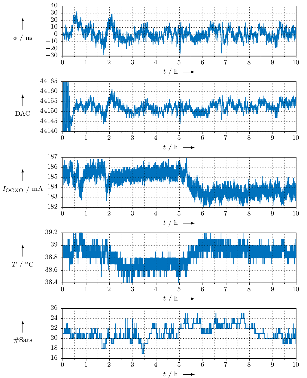
Here is the same plot, but over a much longer time period.
In the following posts I will illustrate my GPSDO in more detail.
