This is a gallery of nice RF equipment that I collect or that I have built.
Work
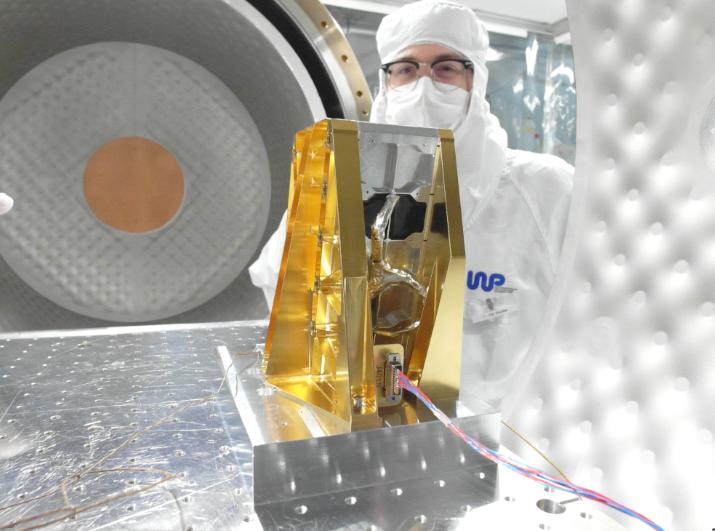
This is me in the clean room, for the assembly and test of some RF parts for the Arctic Weather Satellite.
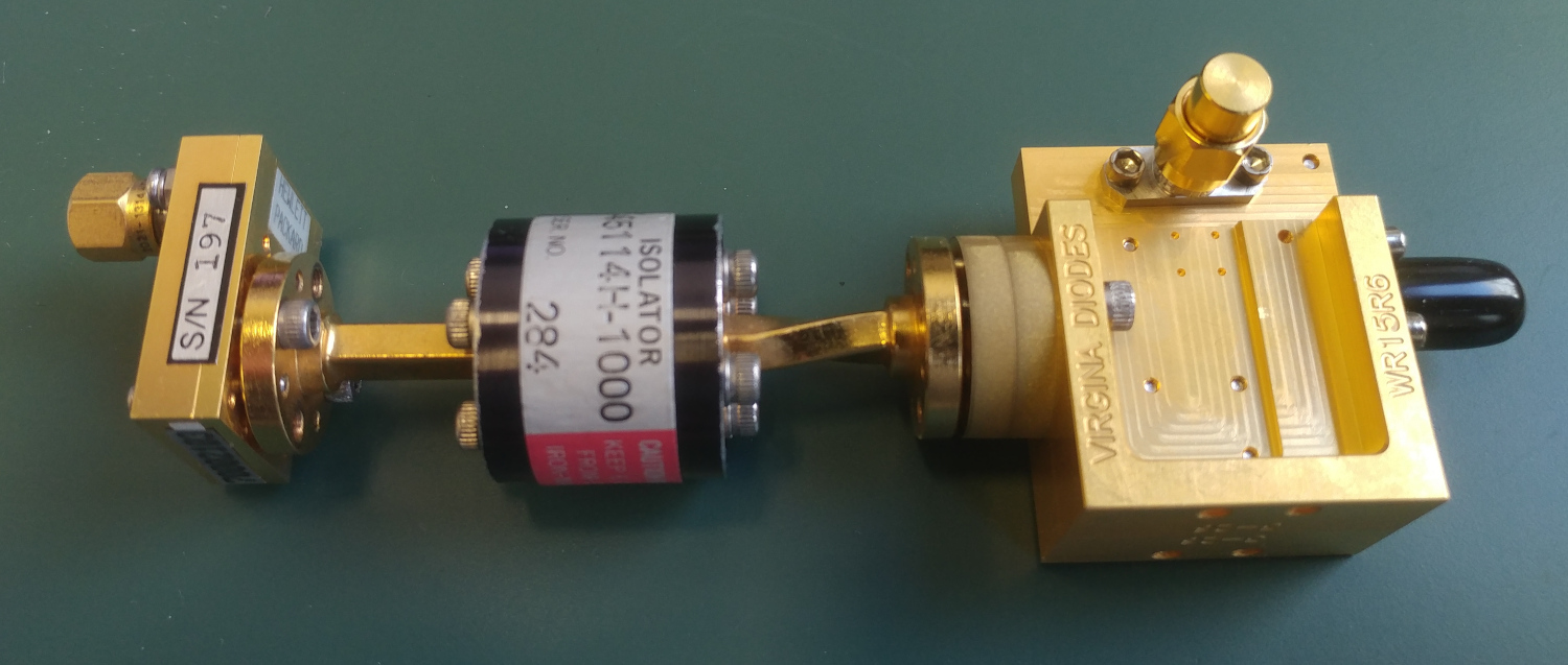
My WR15 waveguide directional coupler, used in the TEMPERA-C instrument for temperature measurement in the atmosphere. It is used together with the horn antenna, also shown below, which is a corrugated, ultra-gaussian horn antenna with circular waveguide. The transition from circular to rectangular waveguide is done via an orthomode transducer.


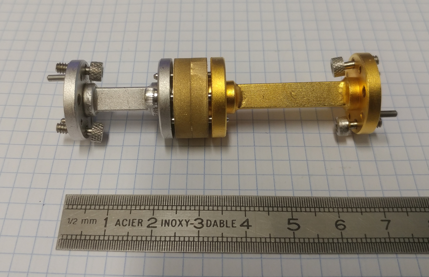
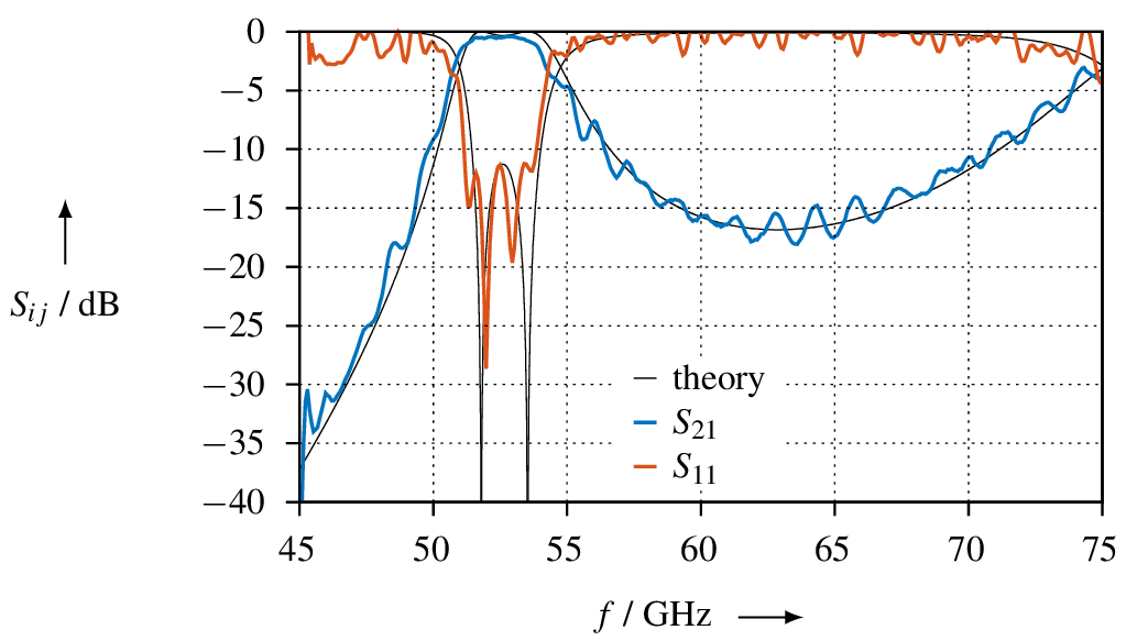
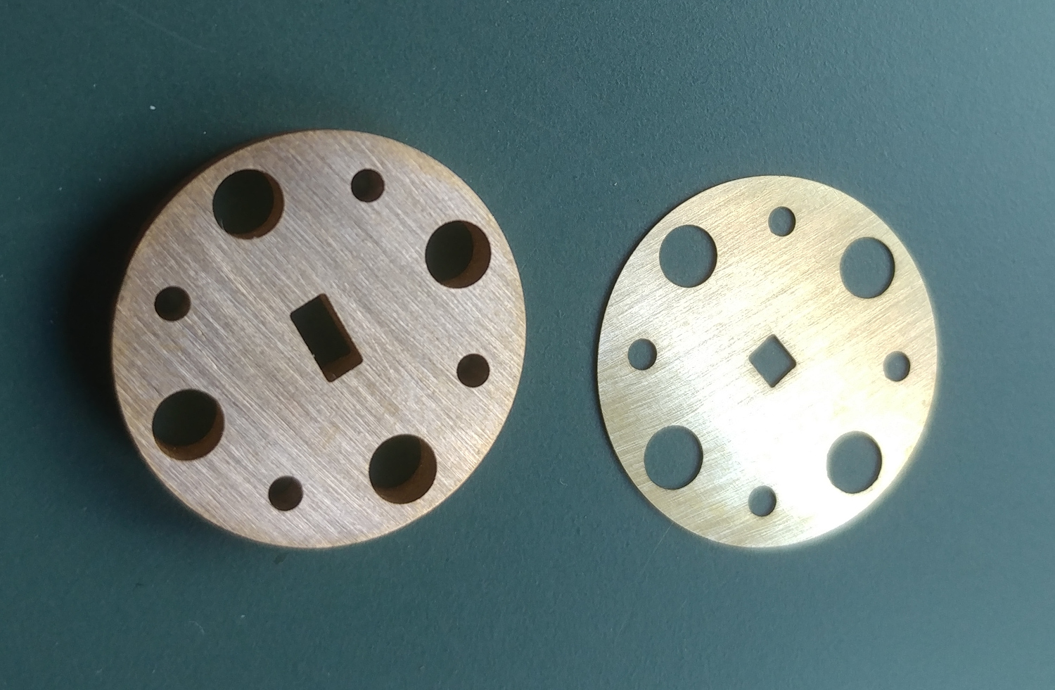
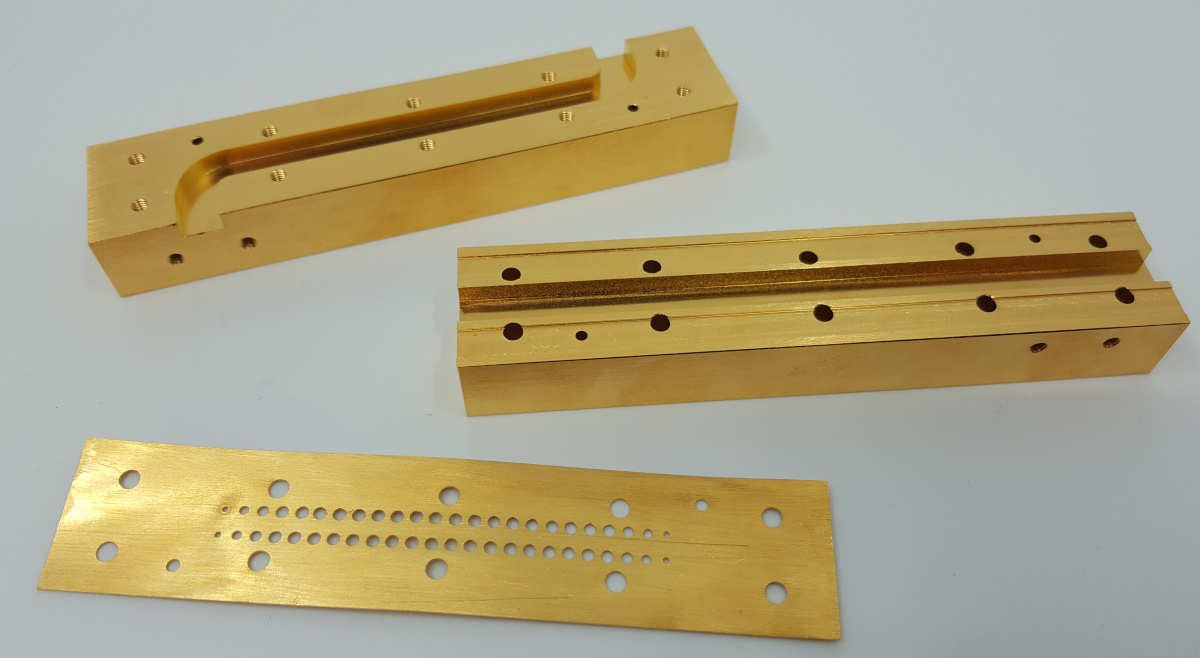
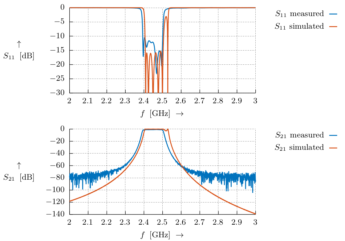
This is a waveguide bandpass filter for V-band (WR15) which I designed using precision water-jet cut shims. Left: two pieces of waveguide with the filter (approx. 10mm brass section in the centre) in between. Right: measurement of S11 and S21 of the filter. This was only a “quick & dirty” test without a proper TRM calibration – this is why the traces do have quite a bit of ripple. The filter will be used in a microwave radiometer of the University of Bern.
The filter is constructed with shims having different thicknesses and different waveguide dimensions. The shims are then stacked on top of each other and aligned precisely using dowel pins (left). The right picture shows the filter at its final mounting positions: it is used as a sideband filter in front of the WR15 mixer which mixes the 52 GHz to 54 GHz band to 3.7 GHz IF.
The link below is a paper from IEEE where I contributed some data to (for the section “mirror losses”).
RF devices and stuff made by me
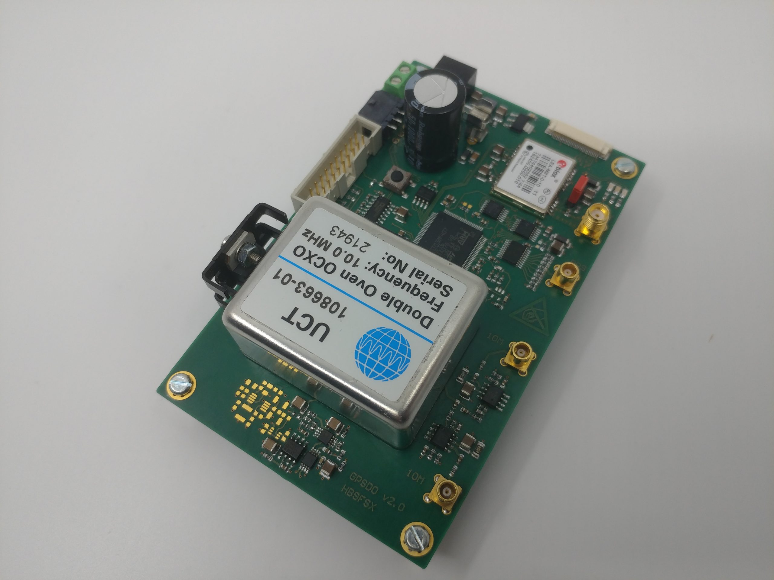
Thsi is my GPS frequency standard providing 10MHz and a 1PPS signal locked to GPS time:
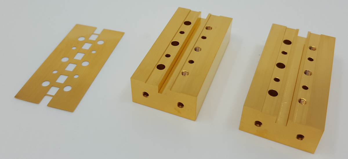
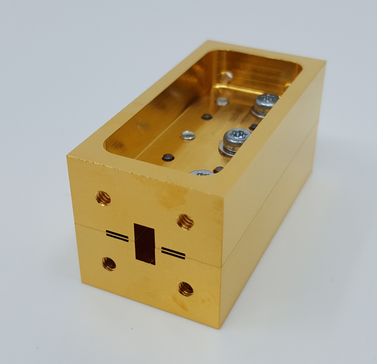
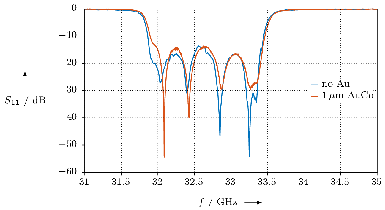
Here is a 33GHz waveguide bandpass filter. It uses a so-called “E-plane metal insert”. I milled it out of two brass blocks; the septum is a 0.2mm thick brass sheet which is precision waterjet cut by microwaterjet. Gold plating is 1 micron AuCo, which is called hard gold and is the same type used for RF connectors.

This is my Ka band (26.5GHz to 40GHz) waveguide directional coupler. It is a Chebyshev design, having 10dB of coupling.
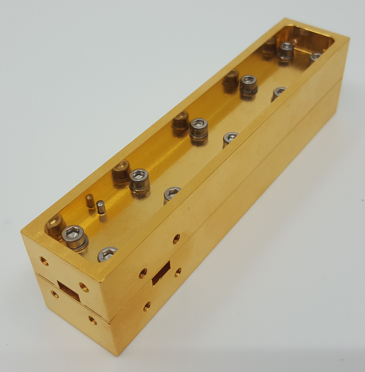

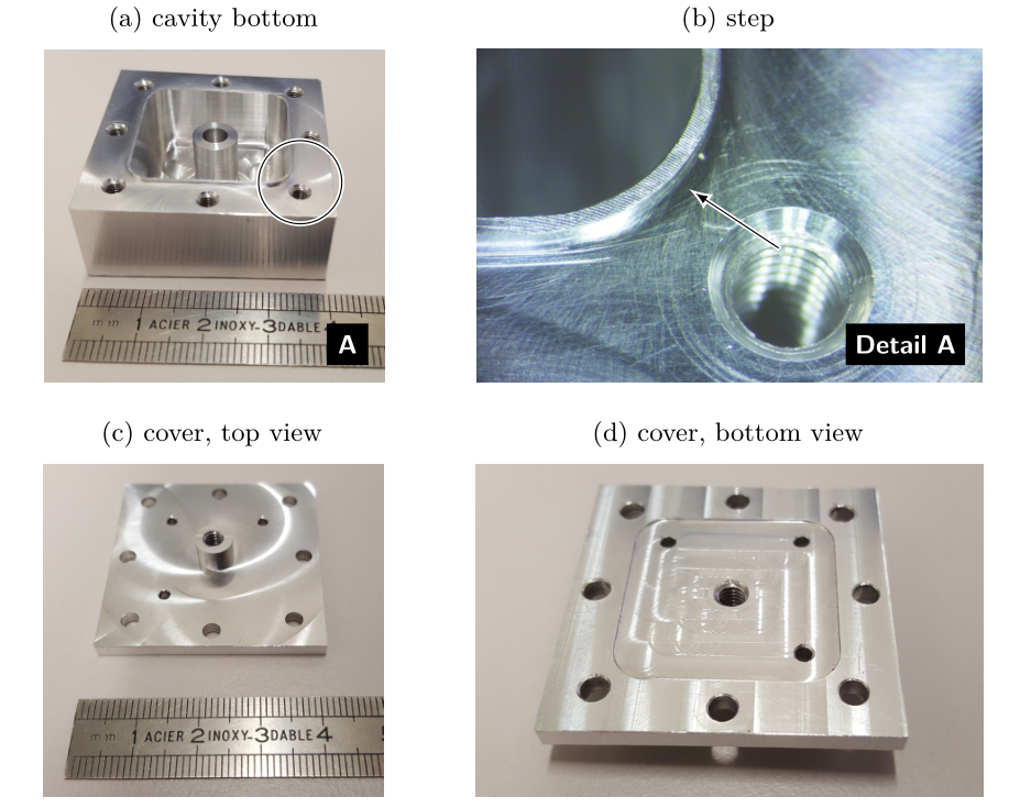
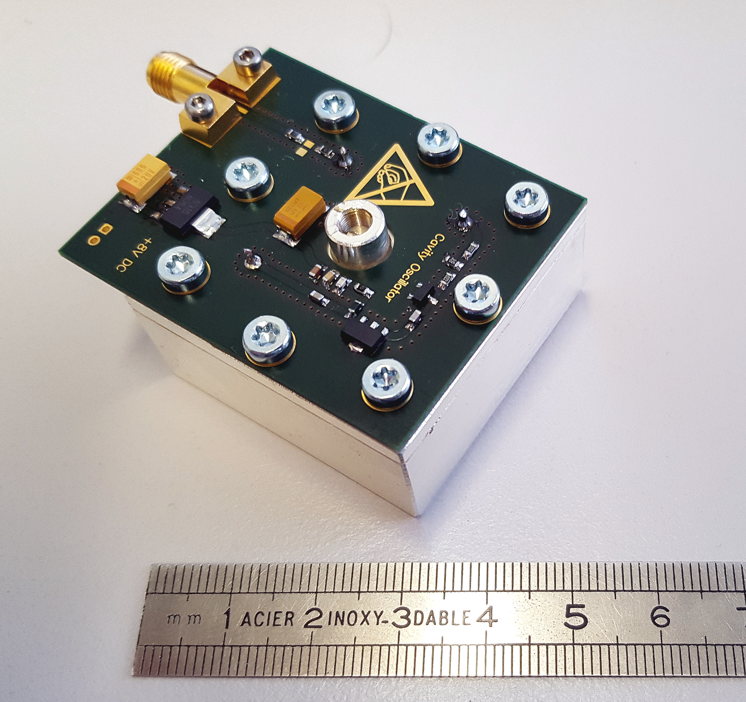
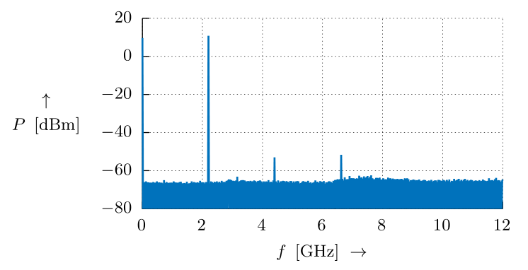
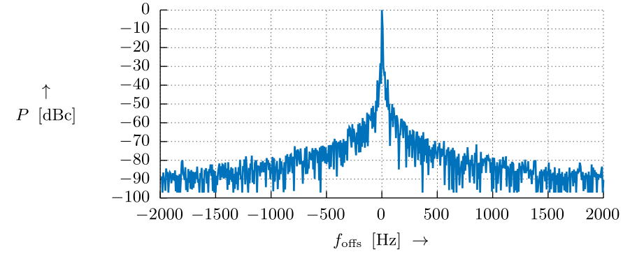
This is my 2.2 GHz cavity oscillator. The tuning screw in the centre allows for frequency adjustment in the 2.05 to 2.4 GHz range. Output power is around 10 dBm +/- 3 dB. The phase noise is incredibly low, but I have not yet managed to actually measure it because I lack a carrier noise test set (HP 11729C is on my bucket list 🙂 ). The close-in spectrum measurement below was made with 10 Hz RBW.
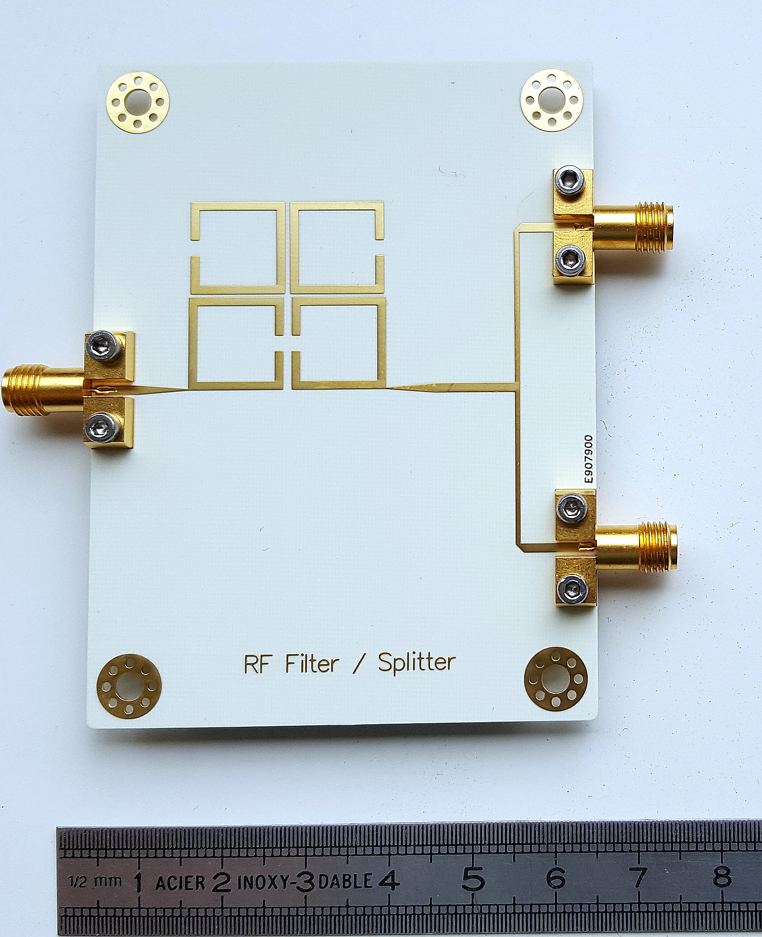
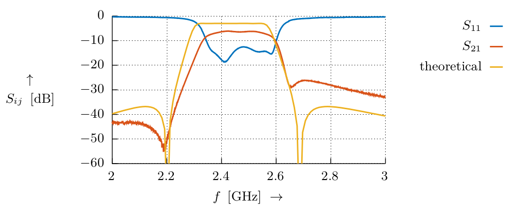
This is a microstrip RF filter using square open-loop resonators. It has quite a nice frequency response 🙂 I designed it with the aid of Dishal’s method and tons of simulations in CST.
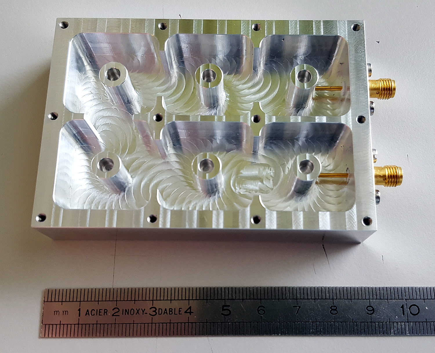
This is a six-pole coaxial cavity filter. As the above microstrip filter, I designed it by applying Dishal’s method, and here I used even more CST simulations.
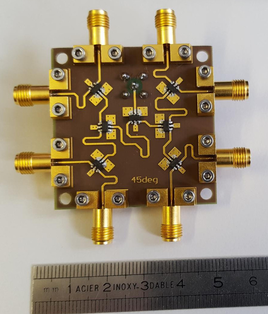
Not so exciting, but looks nice: a 8-way splitter with a specified phase shift between the outputs of 45° at 3.5 GHz!
My test gear
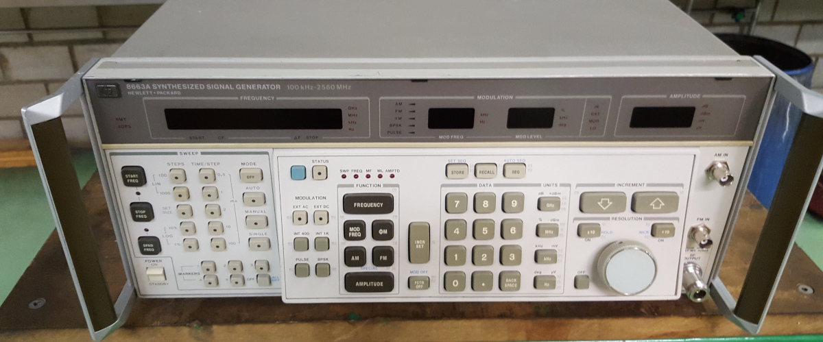
This is the venerable 8663A signal generator. The term “low noise” is definitely not true for its fan. I hope I will be able some day to make a phase noise test set which would allow me to characterise some oscillators.
This is my 5342A microwave frequency counter. It looked quite terribly when I got it from eBay. Besides that, it once has seen some overvoltage – it was configured for 110V but someone plugged it in to a 230V power point… was quite a mess to repair. Almost every single part in the power supply section was toasted! Fortunately this was not the case for the RF section. Besides that, the counter is rated for 18 GHz, but mine has no trouble at all with 20 GHz! At the moment, I have no other sources at hand to test even higher frequencies.

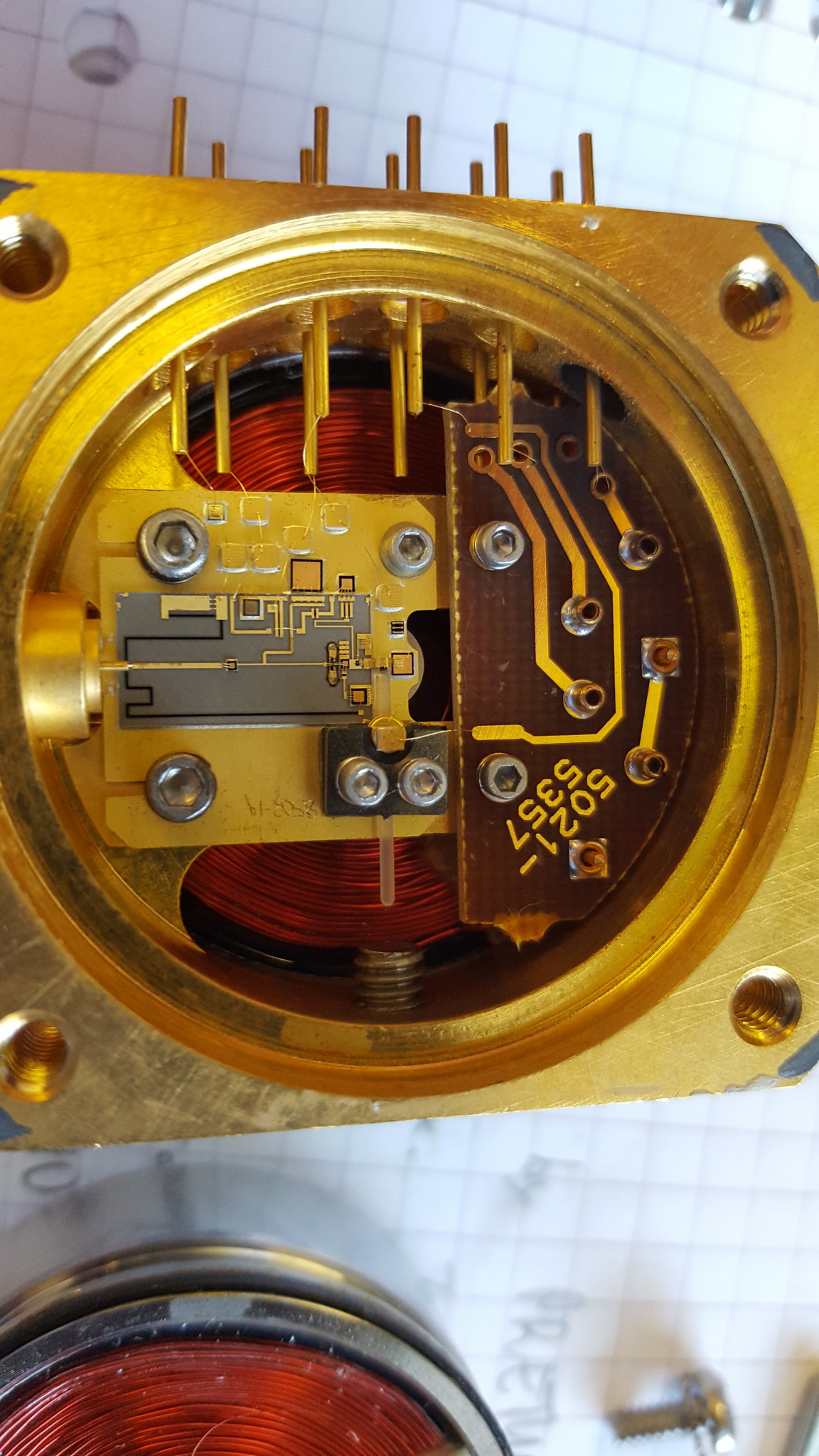
This is my 8341A 10MHz to 20GHz signal generator and at the same time it is the repair story I am most proud of 🙂 because this one had a blown component inside the YIG oscillator, so I had to open that YO and fix it. I couldn’t believe that it actually worked! The other pic shows the YIG oscillator’s interior.

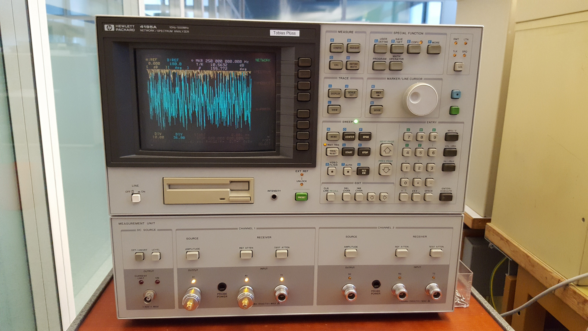
I quite like my 4195A network/spectrum/impedance analyser, even though it goes only to 500MHz. But it is so cool because it can directly calculate the equivalent circuit of electronic components, like a crystal for instance. Comes in handy when a crystal filter is designed!
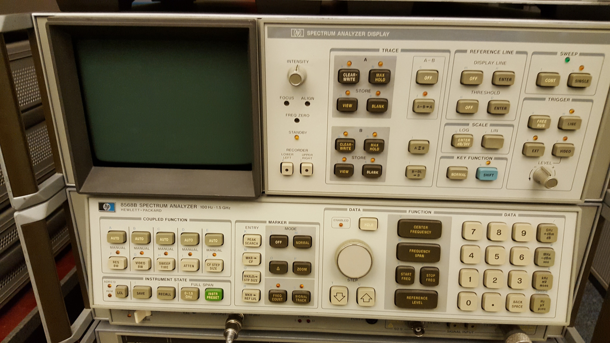
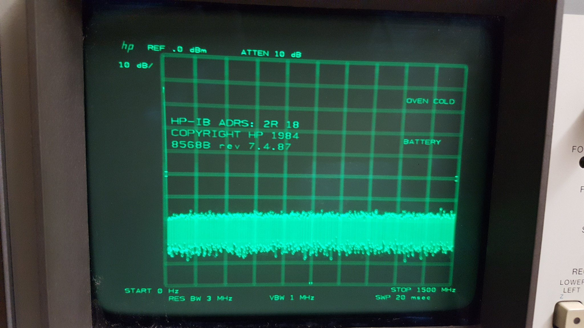
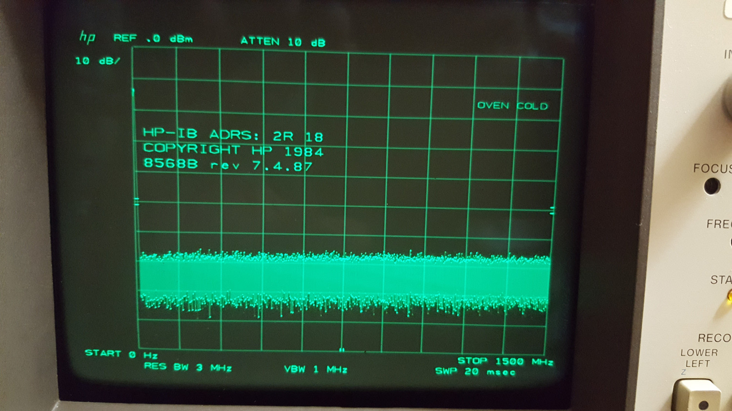
This 8568B spectrum analyser had a quite worn CRT, so I used John Mile’s CRT restoration method to bring the tube back to life. See the before and after pics of the display! Besides that, the SA looked quite ugly when I got it, but now it is in a condition almost like new 🙂
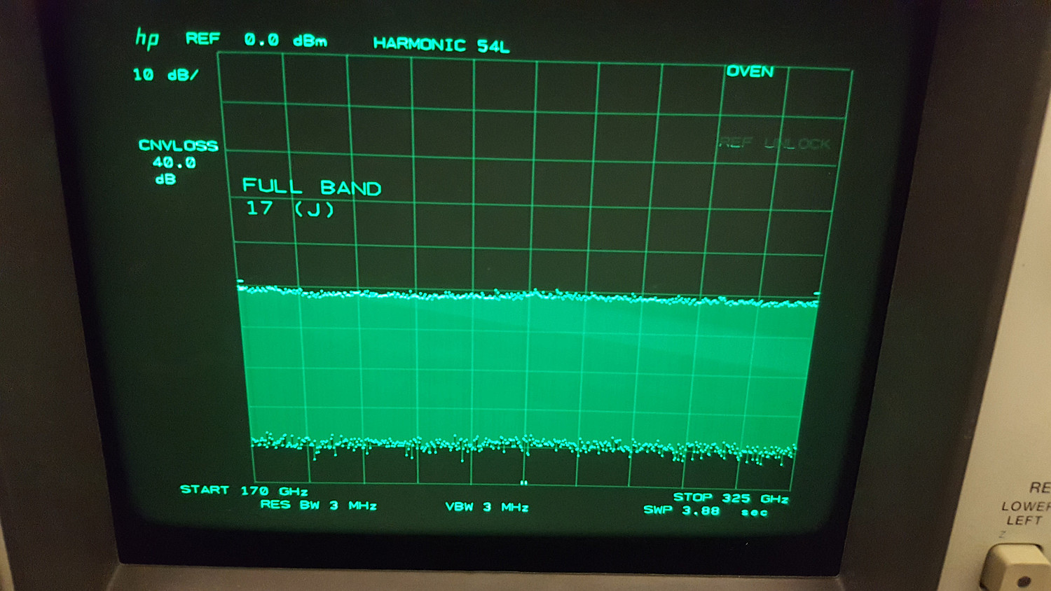
Its larger brother (100 Hz to 22 GHz and 325 GHz with external mixer), the 8566B is also known as the ‘boat anchor’ because it is even heavier (the 8568B’s RF section is mostly empty, whereas the 8566B’s RF section is fully packed with crazy RF things.) The screen of this thing is better than it looks on the pictures. The unit had the problem that sometimes the M/N UNLOCK error appeared. However, this was easily fixed by readjusting the M/N cavity oscillator 🙂 the really cool thing about this spectrum analyzer is that its frequency range can be extended by connecting an external waveguide mixer. Look at the start and stop frequencies below! (however, currently I own only the harmonic mixers up to 110 GHz).

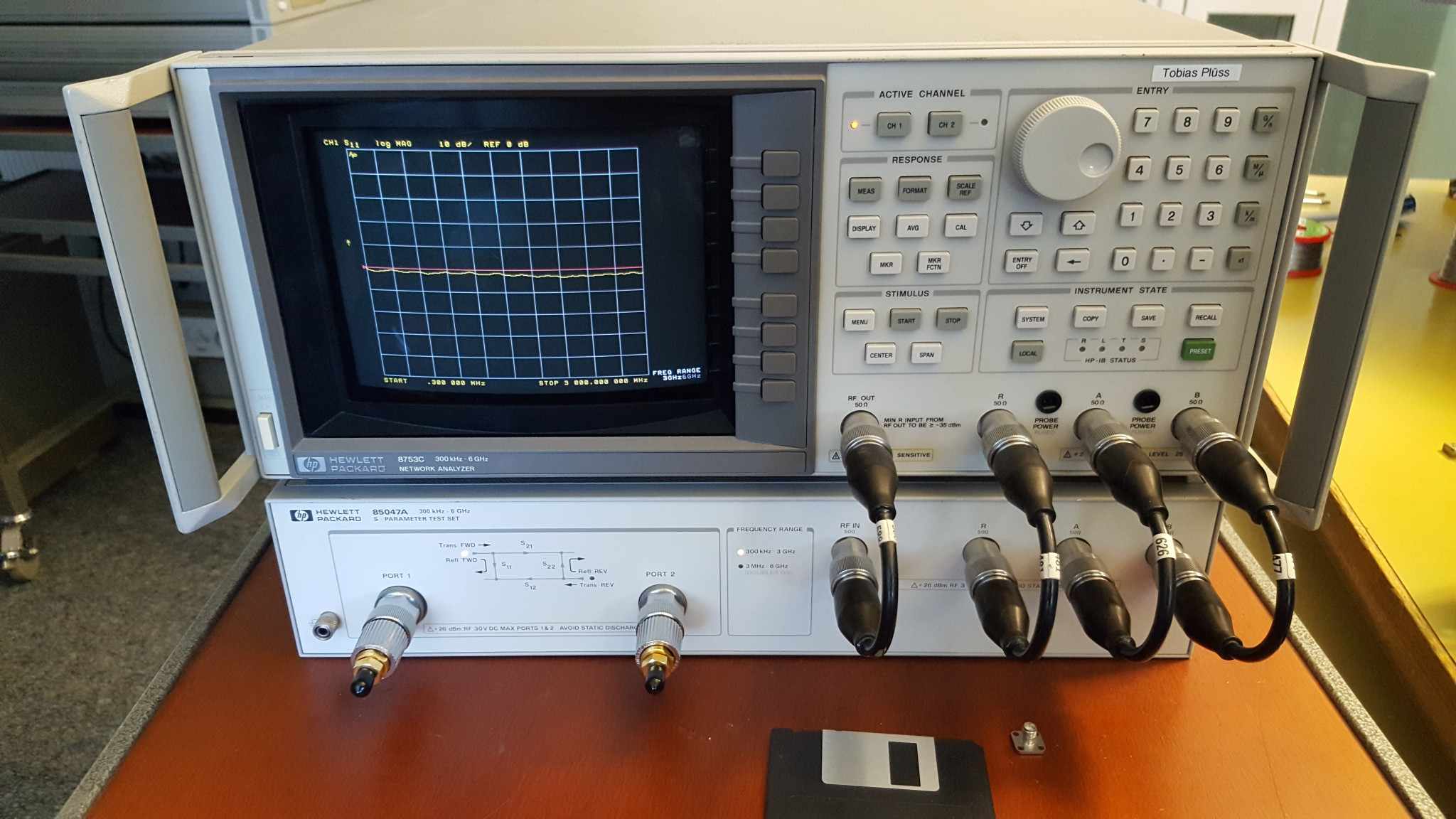
This is my very first RF device, a 8753C network analyser. It is in a really nice condition, almost like new! The A3 source assembly with the YO was broken. Unfortunately, because I had no other equipment available at that time, it was impossible for me to fix this, so I sent the YO to a company which fixed it…