I got a ‘new’ spectrum analyzer, which is a HP 8568B (100 Hz – 1.5 GHz). Unfortunately, it has some problems with the CRT, as well as some noisy traces.
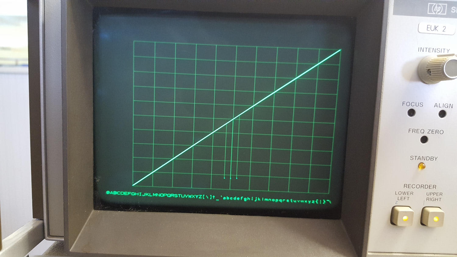
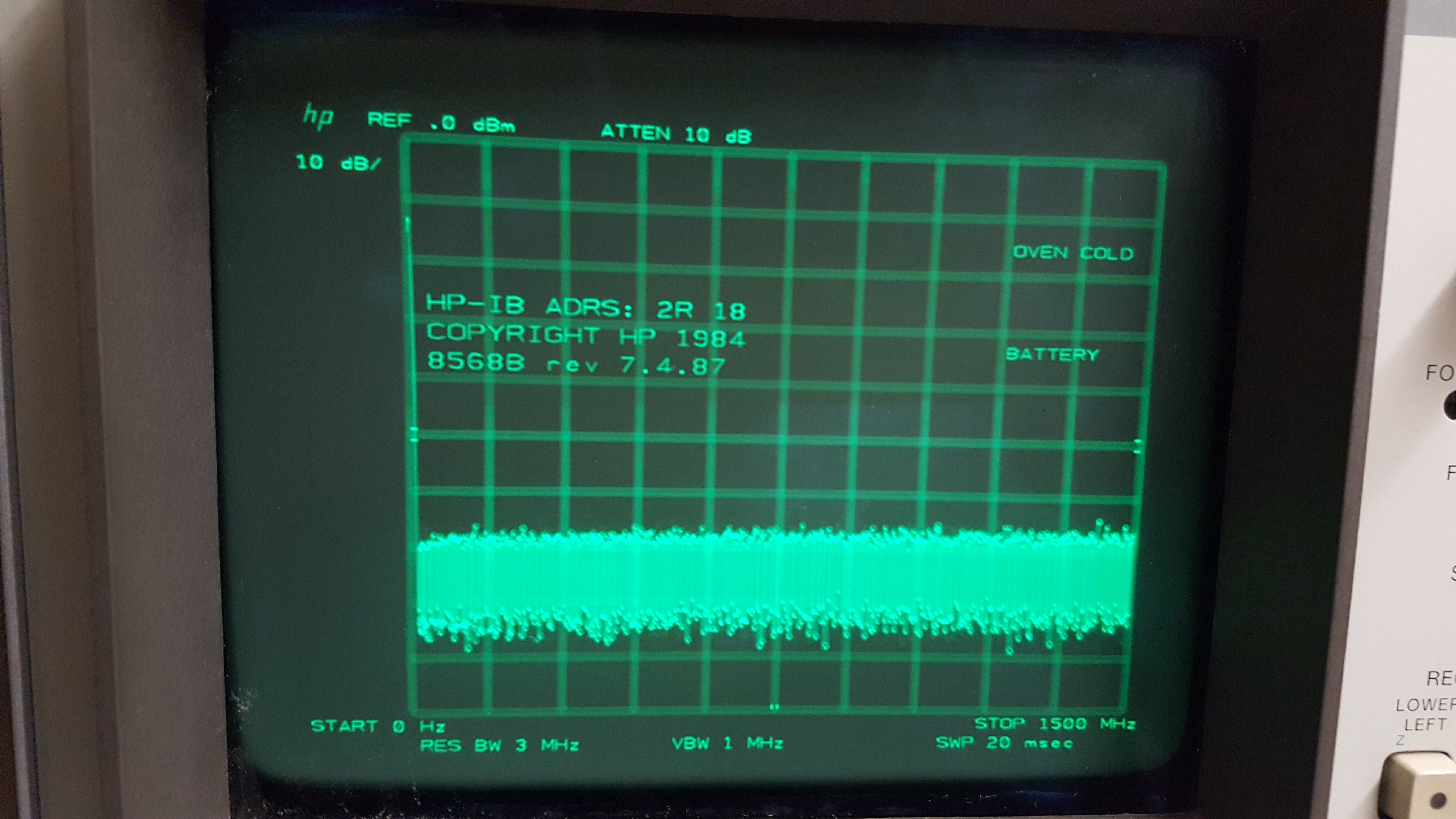
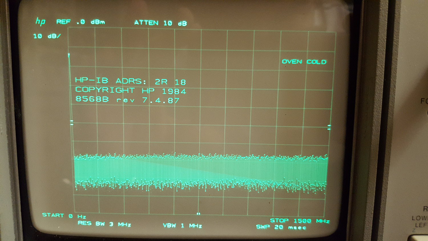
Here is a photograph of the spectrum analyzer’s display when I switched it on:

NO, this is NOT a bad photograph, it is how the display actually looked like! I tried to improve things by adjusting the focus trimmer on the front panel, but no luck.
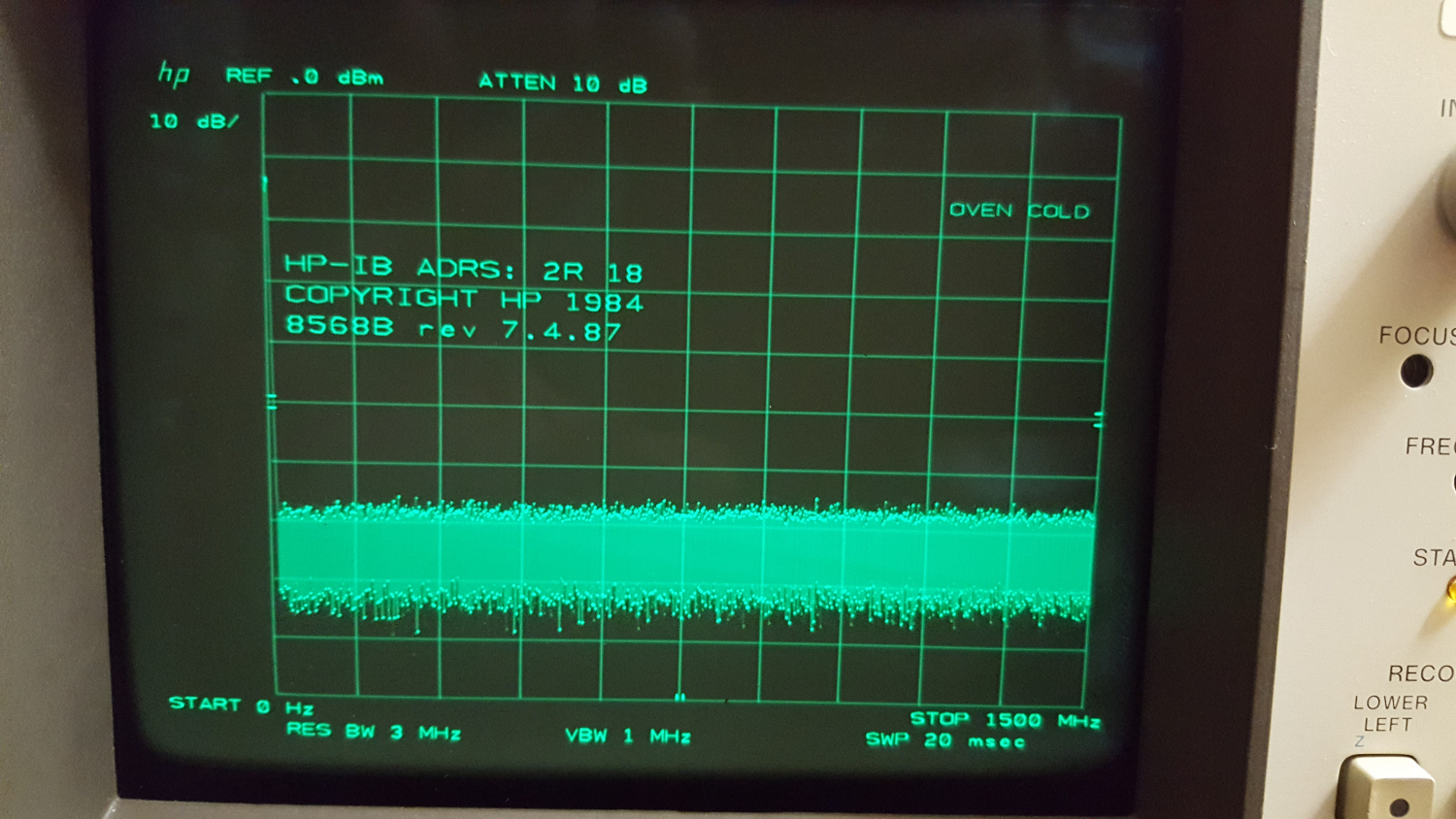
I opened the display and tweaked a bit on the internal trimmers, which yielded some improvemend, but the screen is still very poor.
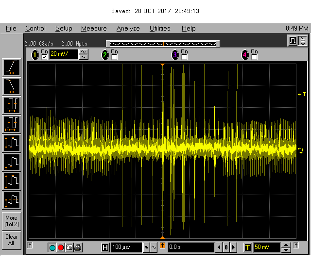
The other problem the spectrum analyzer has is that there is some intermittent noise. Check out this video which I made by connecting the calibrator signal to the RF input:
As one can see, the trace is basically very nice, but at times there is a lot more noise.
First, I did the display test. The result was the following:
So the display test seems fine, indicating that the display ROMs are ok. Good to know!
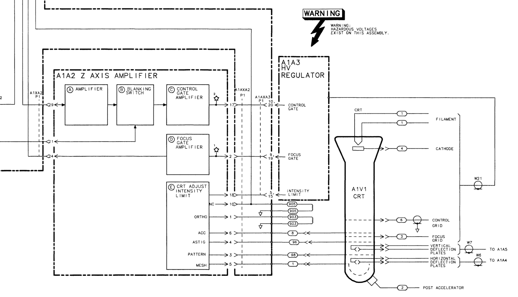
The CRT in the 8568 display is operated as follows: the graticule lines, the traces, and the text are drawn in different speeds. It is actually a vector display. Because the sweep speed of the electron beam is different depending on what it is drawing, different focus settings are required. The voltage on the CRT’s focus grid needs to be adjusted, depending on what is drawn. As far as I know (I have almost no clue about CRTs), this is called the focus gate, and the circuit which drives the focus grid is called the focus gate amplifier.
Since it is possible to adjust the focus such that the text is nice and sharp, I suspected a problem within the focus gate amplifier, which is on the Z-Axis amplifier board:
So, using a highly sophisticated, rocket-science graded test setup 🙂 I measured the focus gate amplifier’s output signal.
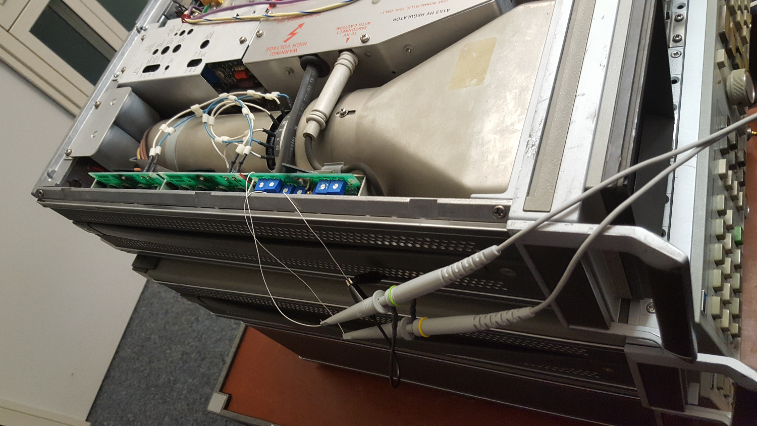
This is the Z-Axis amplifier board with my high tech voltage probes attached:
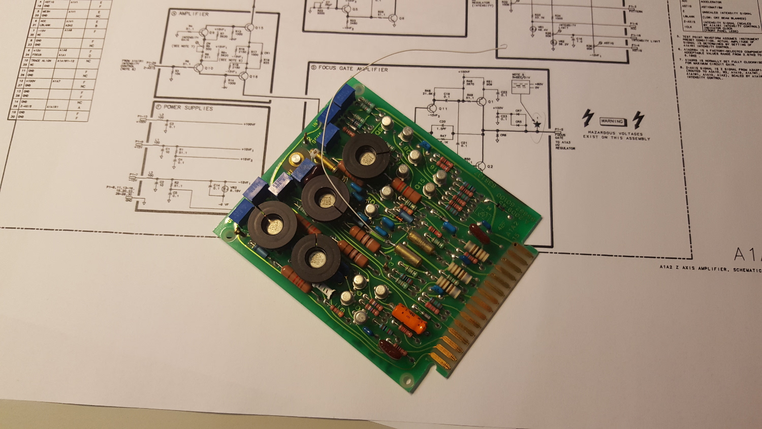
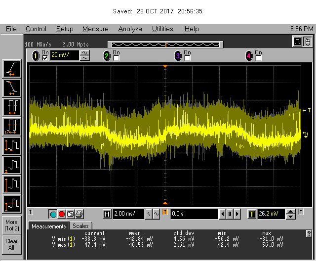
I measured the voltage at the test points 1 and 3, which are the output and input signal to the focus gate amplifier, respectively.
Oh dear, this is quite noisy. According to the service manual, there should be a square wave signal whose amplitude changes when the front panel intensity control is adjusted, but not that noise! Looks like a power supply problem. And this could also be the problem why there is this intermittent noise on the trace! If the power supply is noisy, the YIG oscillator si detuned (sometimes), and this will create the noise on the trace.
OK, looks like a power supply problem. The power supply consists of several boards, one of them being the A1A6 regulator board.
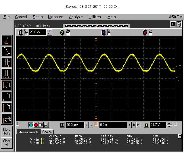
I measured the +/-15V outputs, they were fine (14.995V and -14.984V). Next, I checked the HV oscillator. Signal looks fine as well (+44V max, +10V min according to the service manual).
The ripple on the 15V rails was also measured.
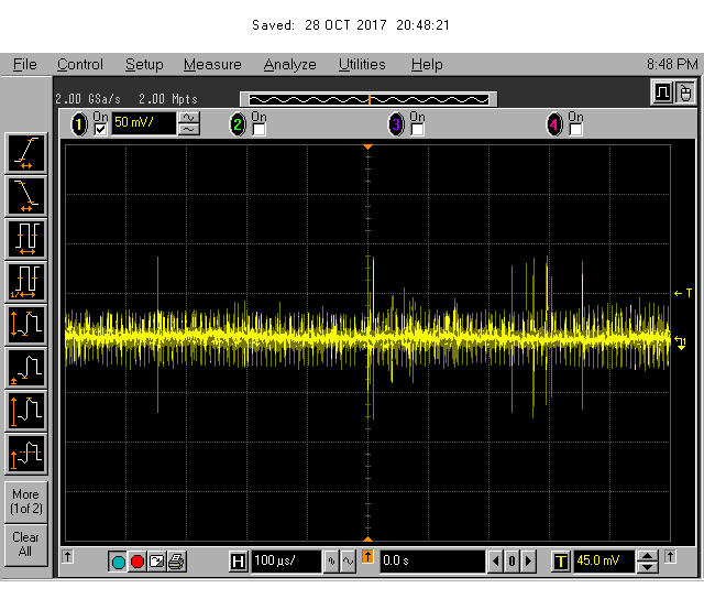
OK, a bit noisy… I also checked the 5.2V power supply. This is on the A1A7 board.
Also not too nice. While I had the whole thing open….

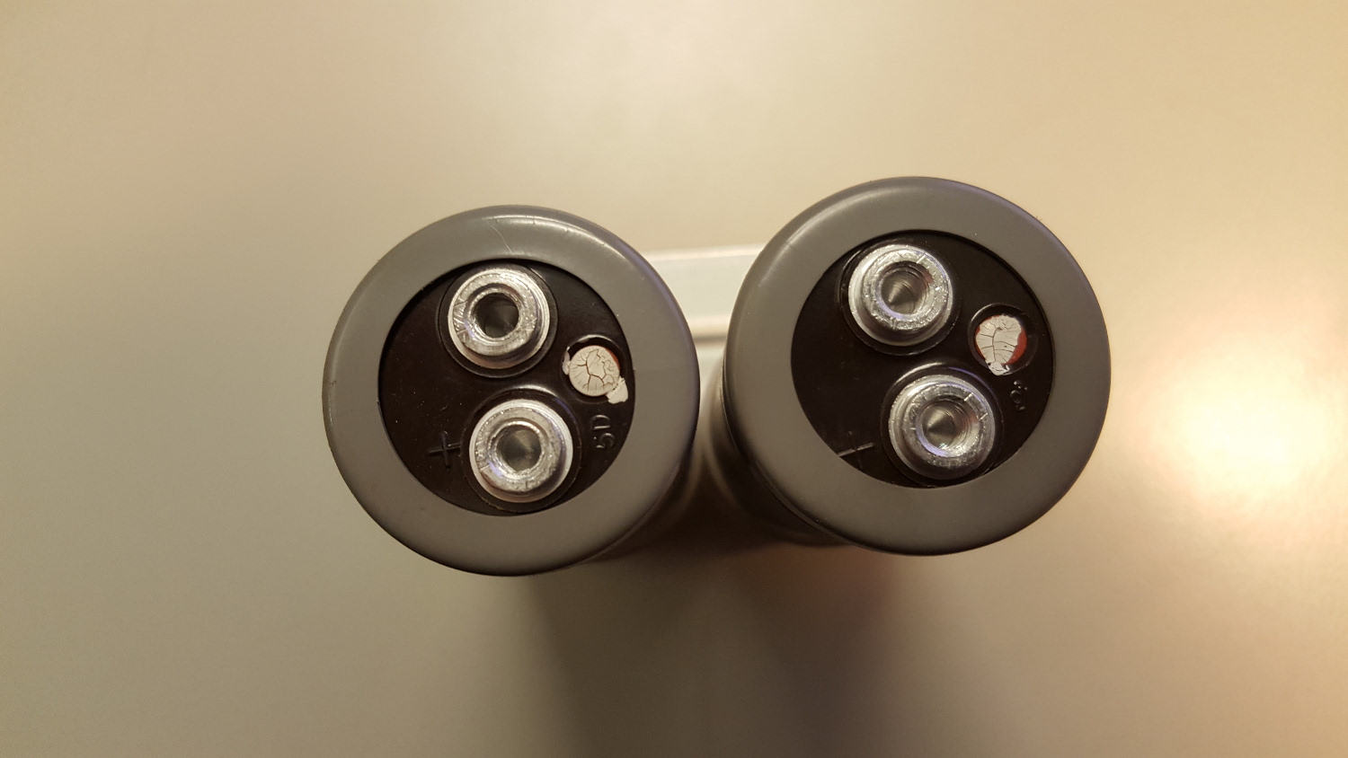
… I also measured the other voltages. 100V is 100.2V, 5.2V is 5.22V, both fine. I decided to remove the capacitors…

… which looked fine.
I also measured the ESR of these electrolytic caps using a 4262A LCR meter. The reading was around 100mOhm for all caps, which seems good to me.
More to come, so far, I have not yet found the problem! 🙁
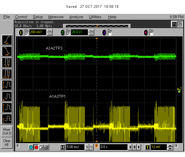
UPDLATE 1: I measured the output signal of the A3A2 intensity control assembly and compared the output signal with the A1A2 focus gate signal. Here it is:
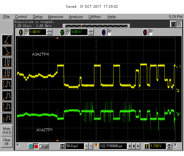
As one can see in the lower trace, there is some noise generated *somewhere* within the instrument. But I have no idea whether these additional spikes are the reason for the unsharp graticule, yet.
UPDATE 2: I read the page of John, where he shows how he successfully ‘rejuvenated’ a HP 8568 spectrum analyzer display. I was unsure how this exactly works, until I found this page. Since I had no idea whether the problems with my CRT came from a noisy power supply or whether it really was a weak tube, I decided to give this rejuvenating procedure a try.
I left the 8568B disconnected from the mains for several days to let the HV capacitors discharge (I am a bit scared of high voltages). Then I opened the high voltage compartment…
and did, just to be sure, the CRT discharge procedure as shown in the service manual, using a screwdriver which was connected to chassis ground with alligator clips.
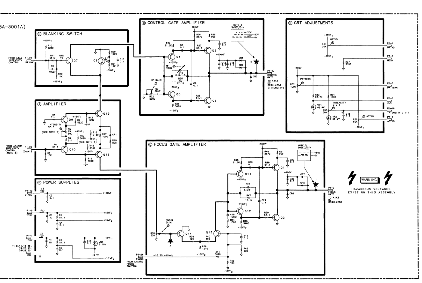
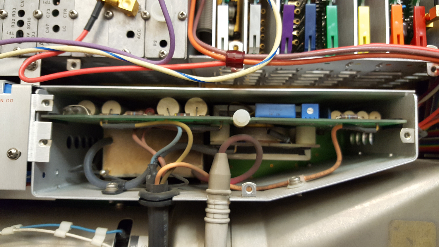
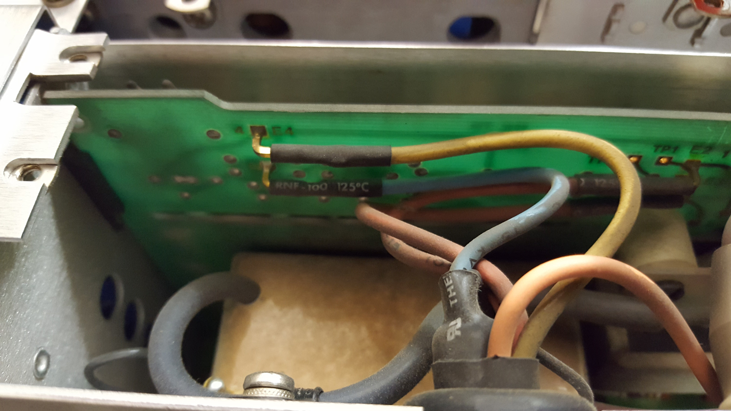
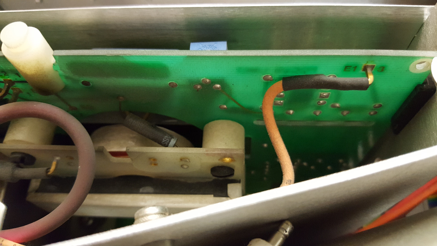
This is the relevant part of the schematics, taken from the service manual:
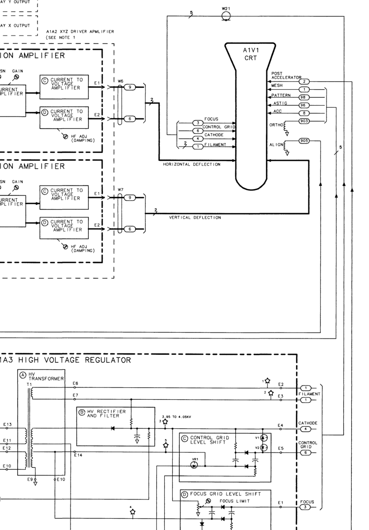
The yellow wire is the cathode, whereas the blue wire is the control grid. The brown wire ‘E1’ is the focus. The filament is connected to the two dark brown wires in the center.
I disconnected the whole cable harness W21. Then, I connected a HP 3616A power supply to the filament, and a HP 6614C power supply (which has an output voltage of up to 100 volts) between the cathode and the control grid, negative lead on the cathode. The current limit on the 6614C was set to about 20mA.
I then turned the filament power supply on and set the filament voltage to 6 volts, the same voltage as John used. Then I turned the 6614C on. At about 40 volts, I had a grid current of about 20 mA. I then increased the current limit to 40 mA, which gave a grid voltage of around 50 V. I let this for a couple of seconds, then turned off the grid voltage, and turned it on a few seconds later again. I did that twice, and both times, the required grid voltage for 40 mA of grid current was a bit lower. I though this would be a good indicator that it is working 🙂
Afterwards, I installed every wire back in its place. I also dismantled the front panel bezel of the CRT to clean the glass.
After I installed the cover for the high voltage power supply, I wanted to see whether I was successful 🙂 this is the CRT before I had done anything:
And this is the CRT with the glass removed, just after rejuvenating:
bezel and glass are still missing, so this is with the glass back in its place:
Wow, what a nice, clear, sharp and crisp display! it definitely worked. And the cool stuff is, the focus stays nice and sharp, no matter what intensity is used! it looks like I have successfully rejuvenated my tube. YES! The display is actually even nicer than on the photographs because my smartphone camera is unable to make a proper snapshot of the CRT.
You do nice work. Thanks for sharing it.