When I wanted to build a diplexer, I read that this can be done by using a highpass anda lowpass filter. But what if someone wants to make a multiplexer, or if one wants to use bandpass filters?
For the design of bandpass and other filters, I use the nice tables made by Zverev. Normally, the filters used for RF things are doubly terminated, which means that there is a load impedance (usually \( 50\,\Omega \)), as well asa source impedance (which is normally the same, \( 50\,\Omega \)). However, there is another class of filters called the singly terminated filters, where the load has a impedance \( \neq 0 \), but the source may have an impedance of \( 0\,\Omega \). Such a filter has following properties:
- in the passband, it presents to the source the same impedance as the load impedance. This is, when looking into the input port, one can see the \( 50\,\Omega \) from the load within the passband.
- outside the passband, the filter input looks like an open circuit.
In contrast to that, the impedance presented at the input port of a doubly terminated filter (the conventional ones) is \( 50\,\Omega \) in the passband, but highly reactive outside the passband (but not an open circuit!).
This is the typical schematic of a doubly terminated filter (and part of a filter table, which we will use later):
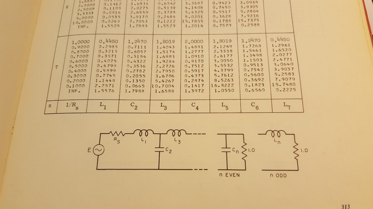
One can see that the filter becomes singly terminated if \( R_S = 0\,\Omega \) which means the same as \( \frac{1}{R_S} \rightarrow \infty \). So there we already have our prototype lowpass element values!
For a 7th order singly terminated filter, one finds the following prototype elements:
- \( g_1 = 1.5576 \)
- \( g_2 = 1.7988 \)
- \( g_3 = 1.6588\)
- \( g_4 = 1.3972\)
- \( g_5 = 1.0550\)
- \( g_6 = 0.6560 \)
- \( g_7 = 0.2225 \)
note that the singly terminated prototype elements are never symmetric, and the order of the elements matters because the filter is open-circuited on one end at the centre frequency, but matched to a desired \( Z_0 \) at the other end!
Next, the lowpass prototype element values need to be denormalised. To do this, the equations
\( L_i = \frac{g_i\,Z_0}{2\,\pi\,B} \)and
\( C_i = \frac{2\,\pi\,B}{g_i\,\omega_m^2\,Z_0} \)are used for the series elements, and
\( L_i = \frac{2\,\pi\,B\,Z_0}{g_i\,\omega_0^2} \)and
\( C_i = \frac{g_i}{2\,\pi\,B\,Z_0} \)are used for the shunt elements.
I made a small MATLAB script where one can enter the desired centre frequency, the bandwidth and \( Z_0 \), and the script directly prints the values for the series and shunt inductors and capacitors. The output from MATLAB looks as follows…
series elements
L =

 826.3000e+000
 880.0000e+000
 559.7000e+000
 118.0000e+000


C =

 15.1000e+000
 14.2000e+000
 22.3000e+000
 106.0000e+000

shunt elements

L =

 32.8000e+000
 42.2000e+000
 89.9000e+000


C =

 381.7000e+000
 296.5000e+000
 139.2000e+000
The code directly outputs nH and pF. So, we can make a schematic, e.g. in MWO or in SPICE. I used MWO for this example.
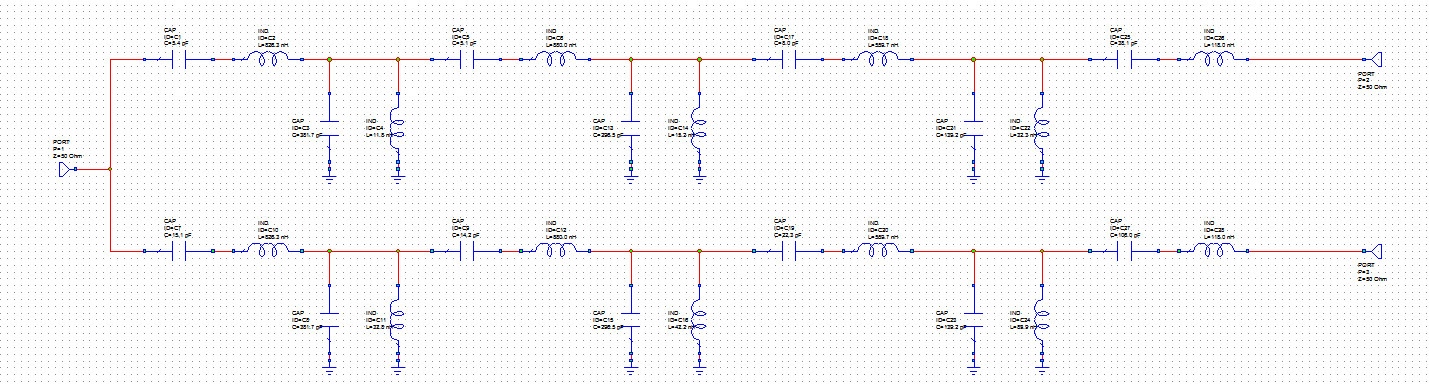
I didn’t round the values to standard element values to see the exact curves in the simulation. For this example, I designed two separate bandpass filters, each having 15 MHz of bandwidth. The centre frequencies are 45 MHz and 75 MHz.
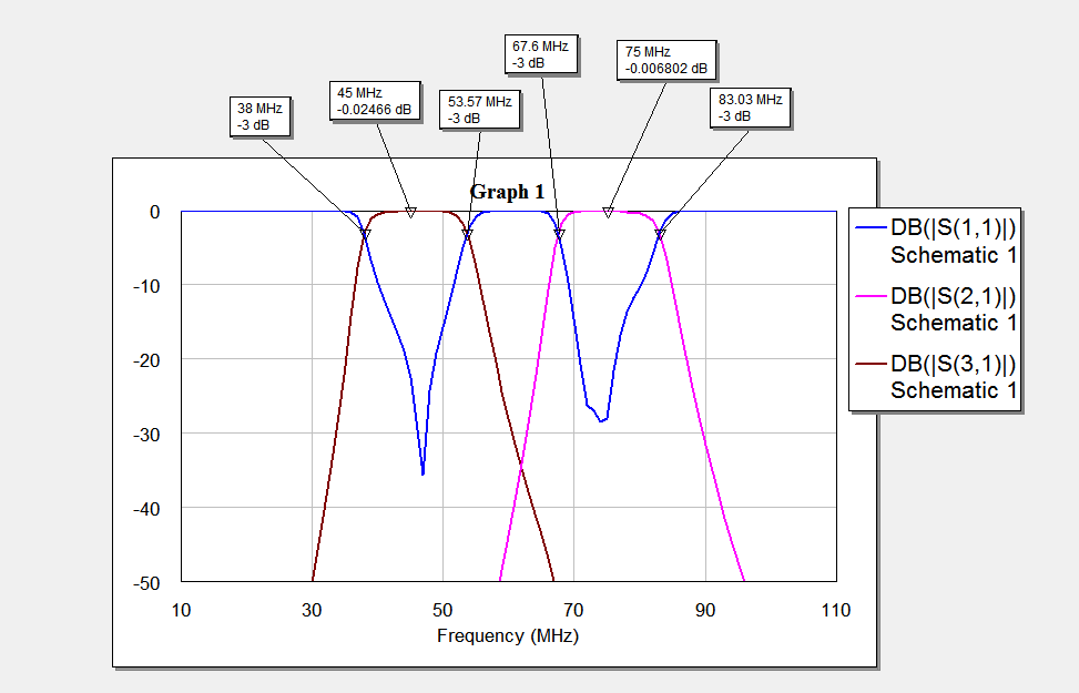
This is the simulation of \( S_{11} \), \( S_{21} \) and \( S_{31} \):
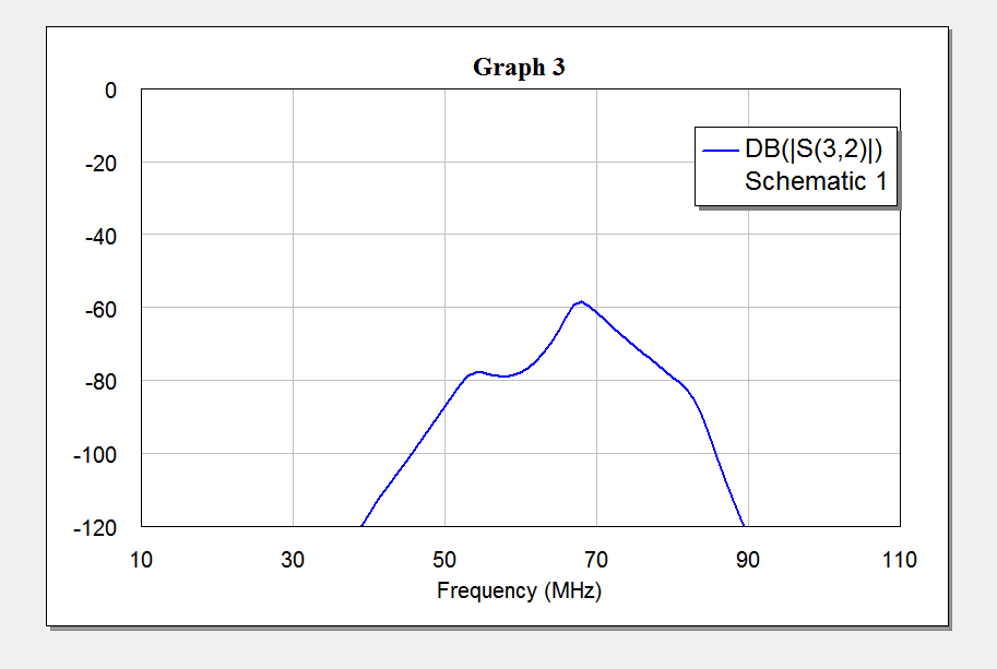
the crosstalk (\( S_{32} \)) is shown here:
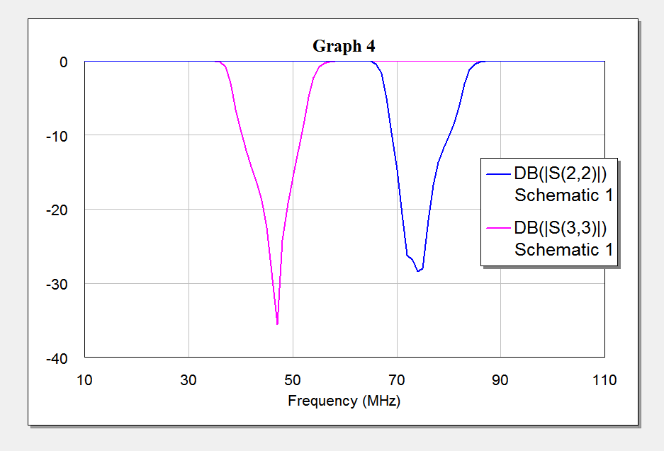
and the output matching (\( S_{33} \) and \( S_{22} \)):
Looks like a really nice diplexer! using the same technique, it is also possible to make a triplexer or a quadruplexer (or a pentaplexer or whatever).
I have attached my MATLAB file, as well as the MWO project file.
To verify the design procedure, I made a simple lowpass/highpass diplexer (the prototype element values can also be denormalised to a lowpass and a highpass filter) and measured it with the trusty HP 8753C network analyser.
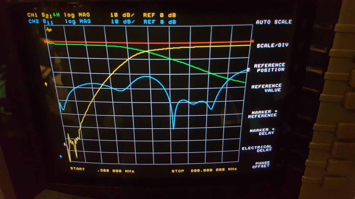
The crossing frequency is 100 MHz; green trace is the lowpass path (with 3 dB cutoff at 100 MHz), whereas the yellow trace is the highpass path (also having its cutoff at 100 MHz). Blue is the return loss.
Of course, having the prototype elements, it is even possible to make e.g. a cavity filter diplexer!
Why so complicated?
Because the ordinary bandpass filters have a 50 Ohms input impedance, it is not possible to directly connect two filters to the same source, because the input impedance of one filter would disturb the other filter.

Good morning,
I downloaded the MWO file and I can not open it.
I have MWO 2001.
I read your website frequently and I like it a lot.
At the moment I am precisely designing (at least trying) a diplexer for a harmonic mixer.
73’s
Rafael Villanueva.
EA7HWX
sorry for my late reply, I will check the MWO file and re-upload it!