In the service manual of the HP 8753C, I read something about a cavity oscillator which is used in this instrument. Later, I read some article in the HP Journal, also about cavity oscillators. Time to build my own!
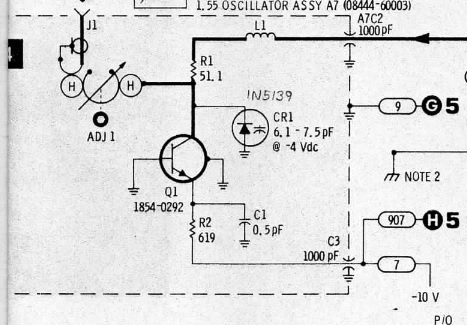
The cavity oscillator consists of a air-filled cavity (guess where its name comes from 😉 ) and some active device. In the HP 8444A spectrum analyser, a BFR90 transistor in negative impedance configuration is used:
I decided not to use the negative resistance configuration, but a MMIC amplifier instead. The block diagram of my cavity oscillator is as follows:

The cavity serves for two purposes. On one hand, it is used as the frequency-determining element in the feedback loop of an amplifier. On the other hand it is also used as a very narrow-band bandpass filter which suppresses any harmonics produced by the amplifier.
I modeled the cavity in CST. My first try was a circular cavity, but a rectangular cavity (with rounded corners) is easier to manufacture and has a higher Q. This is how the cavity looks like:
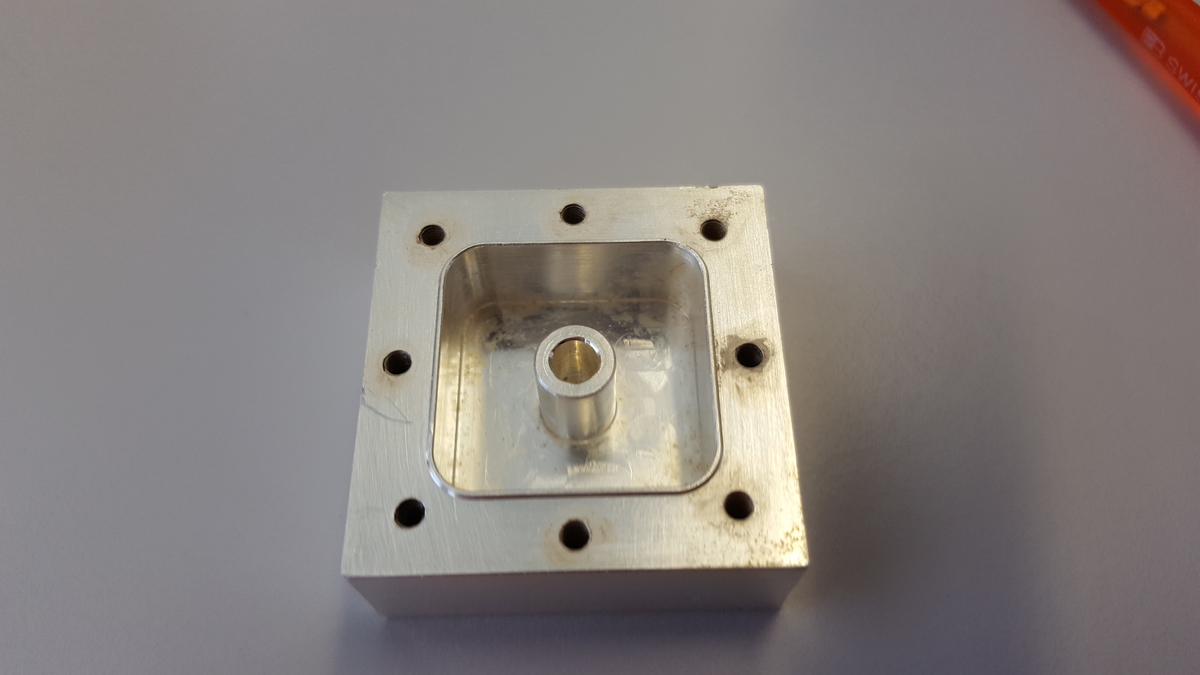
It is milled out of a block of aluminium; afterwards, I silver-plated it to further enhance its Q 😉 The cavity has dimensions 25mm square and a height of 12mm. The centre rod is 8mm in diameter. The hole in the middle is for a tuning screw which protrudes from the top cover. Using CST, I calculated the eigenmode, i.e. resonant frequency, as function of the tuning screw penetration depth. Following chart shows how the frequency depends on how deep the tuning screw protrudes into the hole.
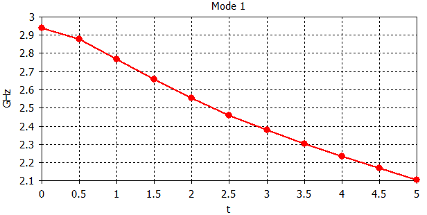
(t is the tuning screw’s depth) Since I wanted my cavity oscillator to operate at 2.2 GHz, a tuning screw depth of approx. 4.2mm is sufficient.
In the next step, I made a small PC board which contains the attenuator, a microwave Schottky diode as limiter, and a AVT55689 MMIC amplifier which I found in my junk box. The electronics board is coupled to the cavity by means of 3 short pieces of wire:
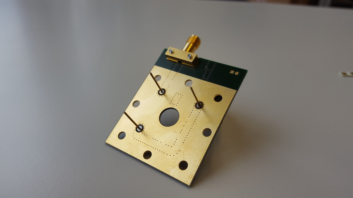
For stability, a 3mm thick piece of aluminium serves as top cover of the cavity; the 3 wires are fed through small holes within this cover. The PCB is then pressed ontop of this cover with the screws. When assembled, it looks as follows:
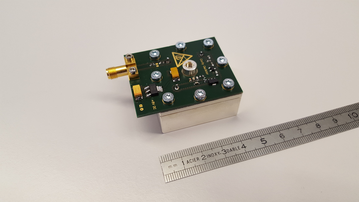
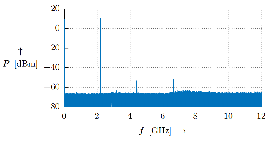
The tuning screw has a very fine thread, so the frequency can be adjusted very precisely. After powerup, I tuned the oscillator to 2.2GHz using a HP 8563E spectrum analyser (unfortunately not mine 🙁 ) as frequency counter. Below is a chart of the oscillator’s output spectrum. Note how nicely the harmonics are suppressed! output power is around 12 dBm, and therefore it is sufficient for a mixer, i.e. level 7 with an attenuator pad to force matching.
I also tried to measure the phase noise. However, this is difficult because the cavity oscillator is free-running and therefore subject to thermal drift. When the cold oscillator is powered up, it is quickly heated up due to power dissipation of the voltage regulator. Just after power up, the oscillator drifts with approximately -1kHz/min. I let the oscillator warm up for a whole day (after which it was quite stable) and then measured the spectrum around the carrier:
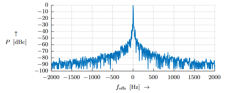
This was measured with a resolution bandwidth of 3 Hz which means that the noise floor would drop further if the RBW was decreased; i.e. phase noise at 1kHz offset from the carrier is better than -90dBc. Noice!
One further thing I tested was the oscillator’s tuning range. The condition for oscillation is that the overall loop gain, including the attenuator, the Schottky limiter, the coupling wires and the MMIC is greater than 0dB and the loop phase is 0°. This is the reason why my tuning range is kind of limited compared to the tuning range of the cavity itself. I measured the tuning range by putting the spectrum analyser to MAX HOLD and then adjusting the tuning screw in both directions as far as possible. This is the result:
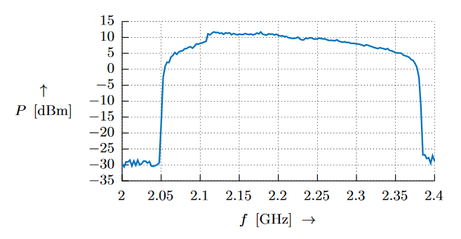
So there is a tuning range of around 400 MHz.
I tested whether it is possible to add a varactor to the cavity oscillator. This would enable the possibility of electronically tuning it such that it could be hooked to a PLL. In my junk box I had some SMV1237 varactors. With one of these I achieved a tuning range of approx. 5 MHz which is just sufficient to compensate for the thermal drift of the oscillator!
Very nice workmanship!!!
I was trying to build the exact same thing a while back MMIC+cavity but I haven’t figured out how to mill a cavity. Do you have access to a CNC miller?
I then turned my interest to build a DRO of ring resonator based one but haven’t have time to do it yet.
Best,
Calvin
unfortunately I found it difficult to get access to dielectric ceramic pucks, so, it was easier to use the cavity 😉
I can publish the drawings if you like.