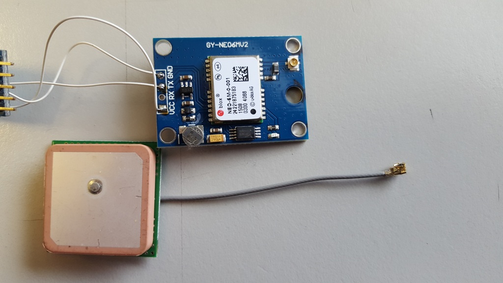
My next project is to build a GPS disciplined oscillator. I have bought a NEO6M GPS module (GY-GPS6MV2) which uses an active antenna. However, there are several drawbacks which I want to fix first.
This is the GPS module as I found it on ebay. I already soldered a UART to USB adaptor to it. One can see that the cable for the antenna is quite short, and besides that, these types of cable are very lossy. Further, with this antenna, I can receive GPS signals only when the antenna is placed near the window, which is not so handy.
First I wanted to add another cable to the antenna with a more useful connector 🙂 quickly desoldered the metal shield…

Interesting LNA design. Apparently, the schematic is as follows:
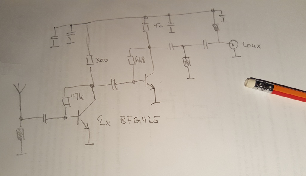
This will probably come in handy later if I need to build a LNA. Next, I soldered in only a piece of RG174 coax cable.
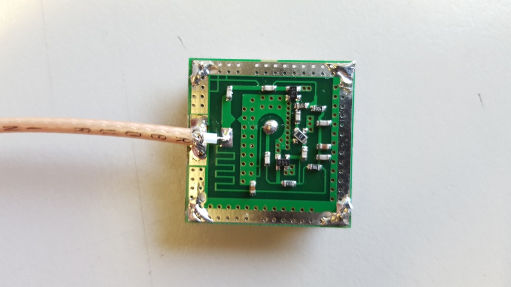
This allows to use extension cables, such that the antenna can be placed near the window, while the GPS module sits on the bench 🙂
However, I still wanted to see whether there is some possibility for improvement. I found an interesting page here. It suggests to use a helix antenna, which is what I want to try.
For the antenna ‘mast’ I used a piece of semirigid coax cable with a SMA connector. The helix itself is made from four pieces of 2mm diameter brass wire which I wound no a piece of pipe with 30mm diameter to form the turns. This is the antenna after I have soldered everything together:
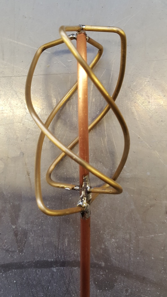
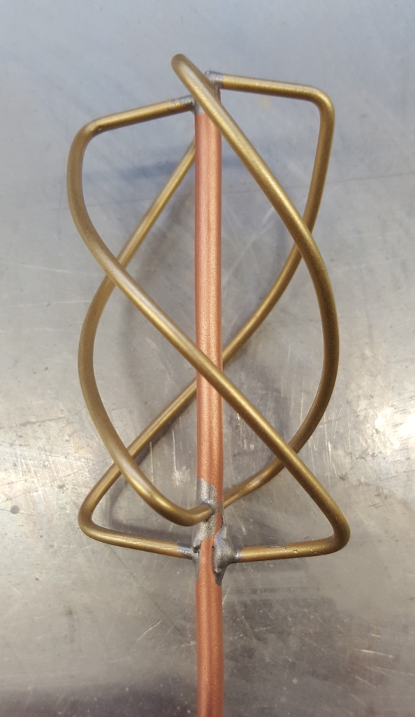
It looks quite ugly, because the brass and the semirigid coax are full of oxides and dirt (and of course because my solder joints are not the best in the world 🙂 ). Therefore I decided to do some sandblasting on the whole thing (however I did not use sand, but small glass pearls, is there something like ‘glass pearl blasting’?). Afterwards it looks a lot better:
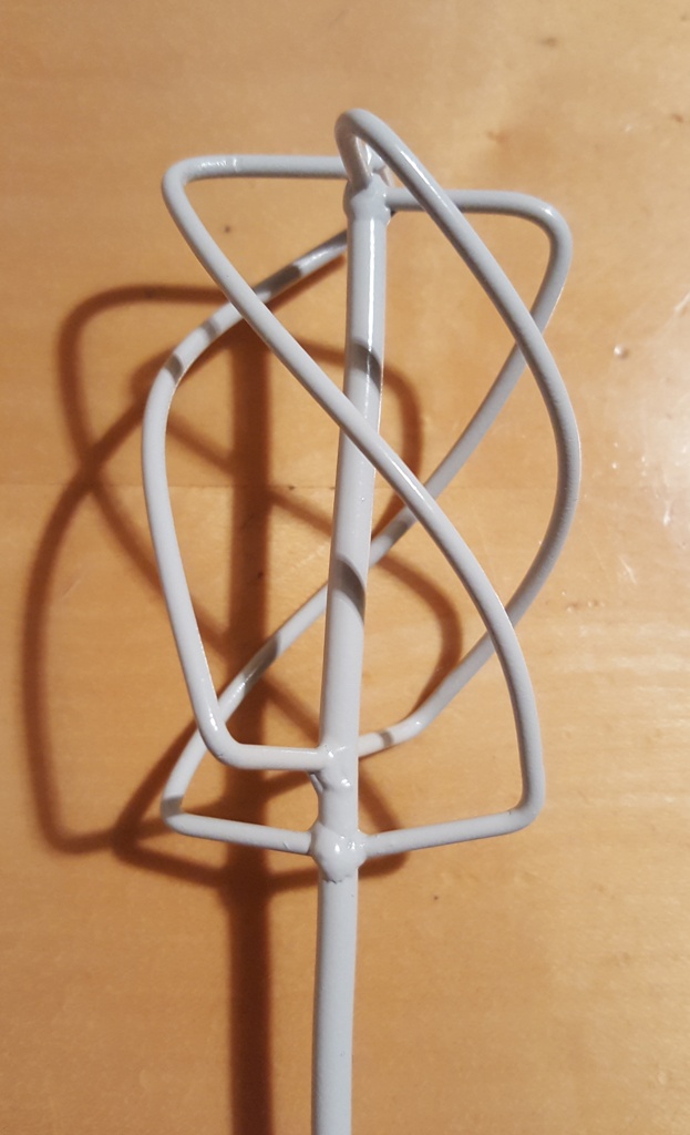
The surface is now a bit rough, which is fine because I am going to paint it (since the antenna will be used in my lab, and therefore should have a lab-grade colour 🙂 ). Voila, using RAL7035 😉
Next, I measured the input reflection coefficient. Measurement conditions were not optimal because I had only approx. 3m of free space above the antenna, but to get a first ballpark figure it should be fine.

-12 dB S11 looks fine for me. I will verify the radiation pattern later! Now, I did a first short test of the antenna. I placed the previous (active) antenna near the window and noted the number of satellites received (it is output by the GPS module in the GPGSV sentence). Next, I used this very antenna without a LNA (note that the antenna is a DC short, so I used a Minicircuits BLK-89+ as DC block) and then I made a small LNA using a GALI-S66. These are my numbers:
| Antenna | # satellites received |
| original antenna (active) | 6 |
| new antenna (passive) | 8 |
| new antenna + LNA | 9 |
so there is a bit of improvement. Not bad! Next thing is to measure the radiation pattern and compare with a simulation.
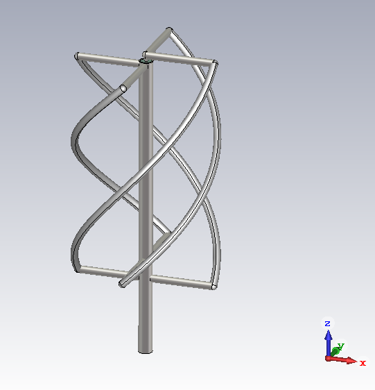
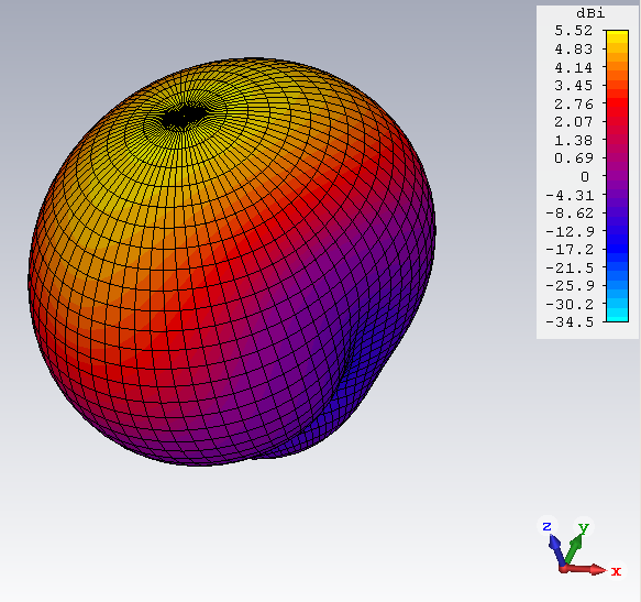
I made a simulation in CST:
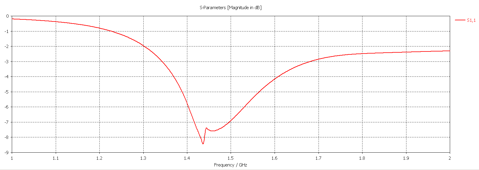
The simulated S11 looks not too bad, even though in reality it is a bit better.
The gain is apparently around 5.5 dBi.
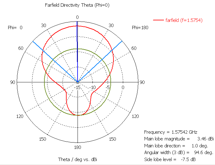

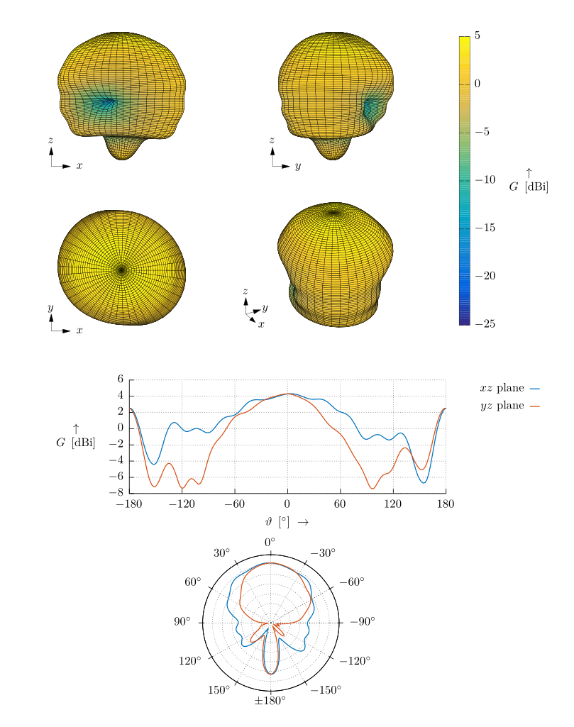
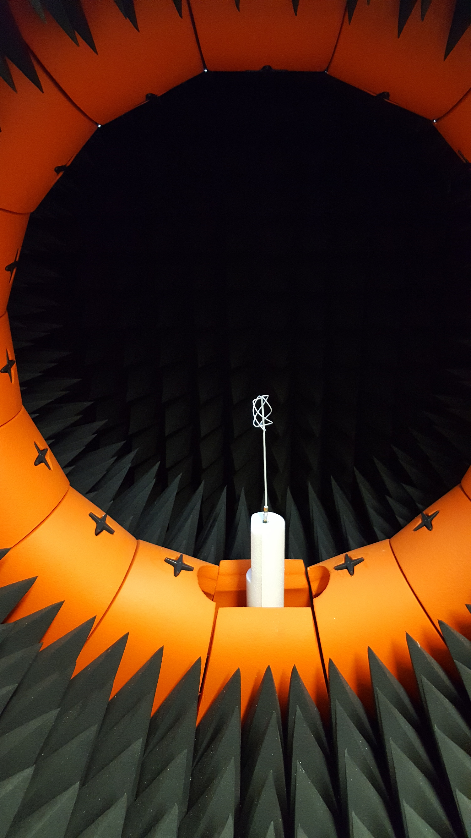
The antenna’s radiation pattern is going to be measured:
The result looks quite nice! The gain is actually a bit smaller than 5.5dBi, but the radiation pattern looks very similar.