As I said, after I made my own waveguide termination, I wanted to make a directional coupler in waveguide. Here is my progress.
There are numerous ways how to make a directional coupler in waveguide technology, like Bethe-Hole couplers, Cross-Guide and so on. Before making one, I wanted to see how commercial directional couplers are made, so I found a cheap one on eBay (probably it was so cheap because it was not a terribly good one?) and dismantled it. This is the coupler before dismantling:
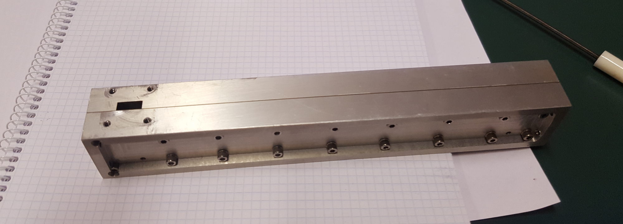
Apparently, it is made of some sort of split-block technique. It is not visible on the photos, but this coupler has three ports, so there must be an internal termination somewhere. We’ll see.

Two ports are opposite of each other, on the short walls of the aluminium block, and the coupler port is on the long wall. After all screws have been removed, this is what we find:

Obviously, this is the coupler port with it’s termination on the right-hand side. The two through-ports are on the other part of the alu block, of which I didn’t make a picture, but it looks essentially the same but the waveguide is straight and has, of course, no built-in termination.
Clos up of the termination. The principle is simular to mine. Often, terminations are made with a simple wedge, but my termination, as well as this one, use a ‘double wedge’, I don’t know a better word to describe it.
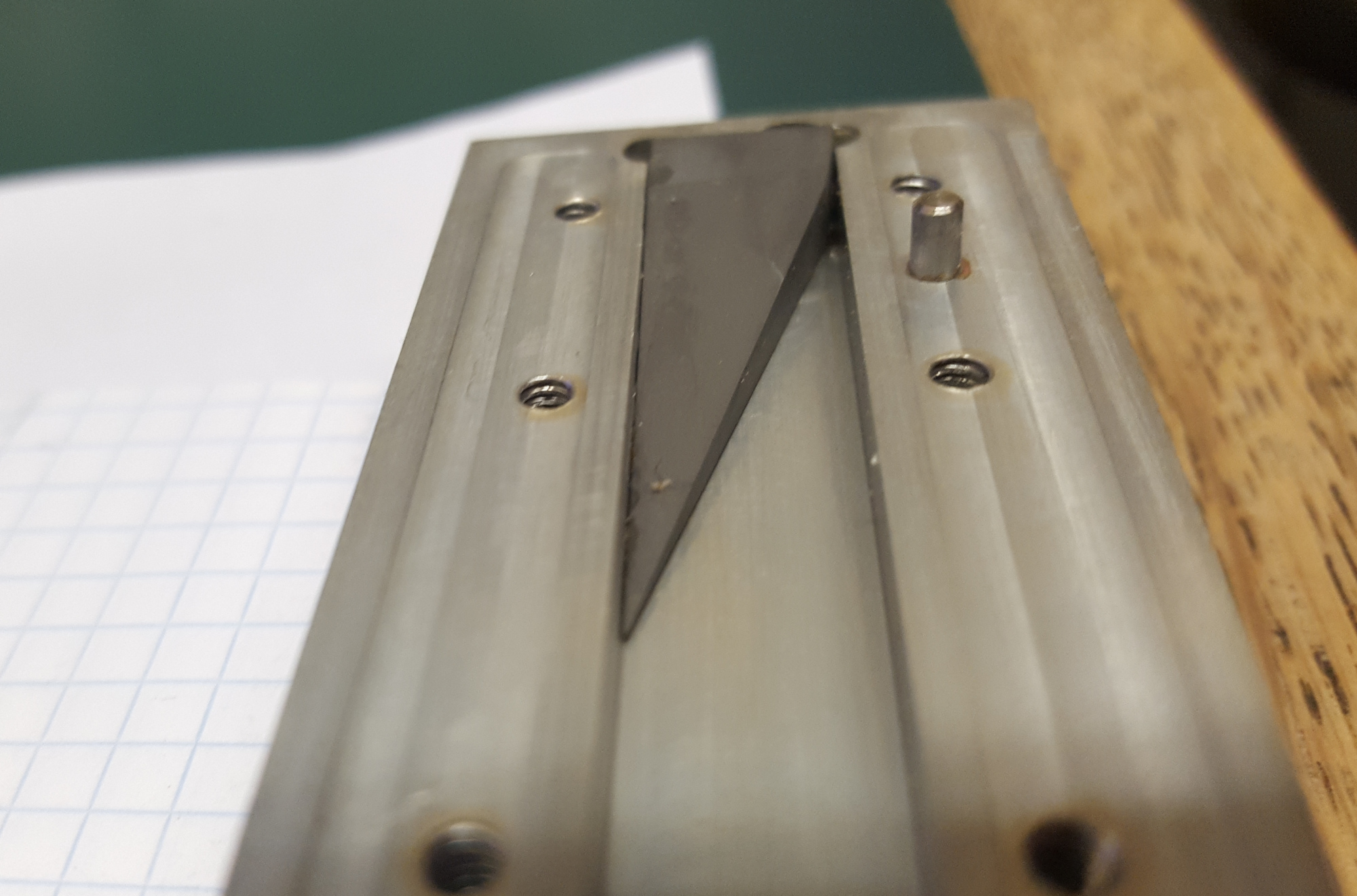
The wedge starts in a corner of the waveguide, where the E and B fields are minimal, and increases gradually in width AND height towards the top wall and the other side wall of the guide. I don’t know what this material on the picture is, but it appears to be some sort of ferrite.
And this is the ‘heart’ of the directional coupler, and also the reason why this kind of coupler is called a multi-hole directional coupler:
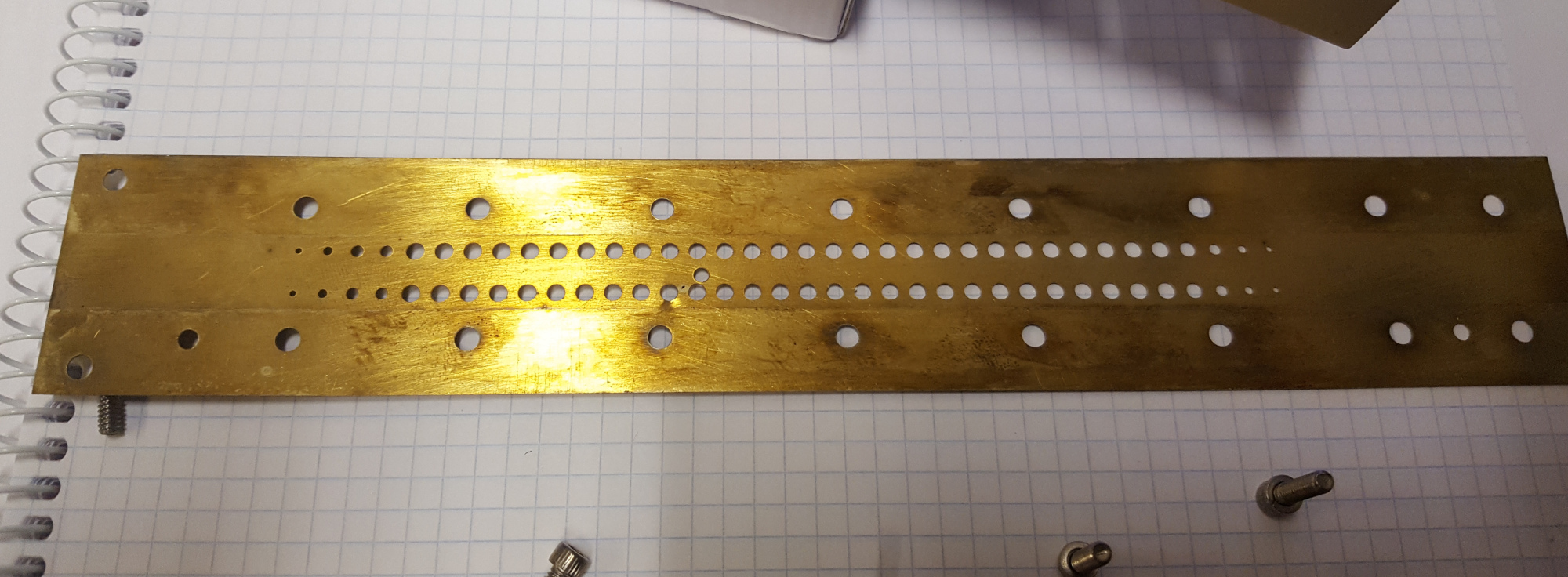
This thin brass plate forms the broad wall between the two waveguides. The holes work similar like in a Bethe-Hole coupler, but since there are many holes, the coupler has a higher bandwidth – the Bethe works only for a very small frequency range.
So the question arises on how this kind of coulers are designed?! of course, Pozar has an explanation in his ‘Microwave Engineering’, but I didn’t get it when I read that section, unfortunately. I’ll give it another try… Fortunately, someone has already solved the problem and made a BASIC program to calculate couplers here. I will use the information in this PDF and the references given to understand how the couplers work and how I can calculate the hole sizes. In the meantime I did some exercises on how to erode this array of holes in to a very thin sheet of metal. Drilling seems to be inappropriate I think because the metal will rip, I think. We’ll see how it goes 😉 hopefully I can soon build a first coupler for test purposes.