I want to do a few experiments with waveguides, this time I try to make a termination. Later I will try to make a directional coupler, so with the aid of the termination I can calibrate the directional coupler and do some measurements at higher frequencies.
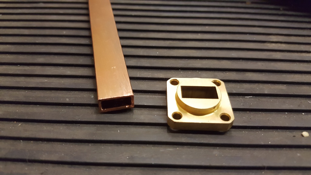
I got a hand on some old stock of flanges and WR42 guides.
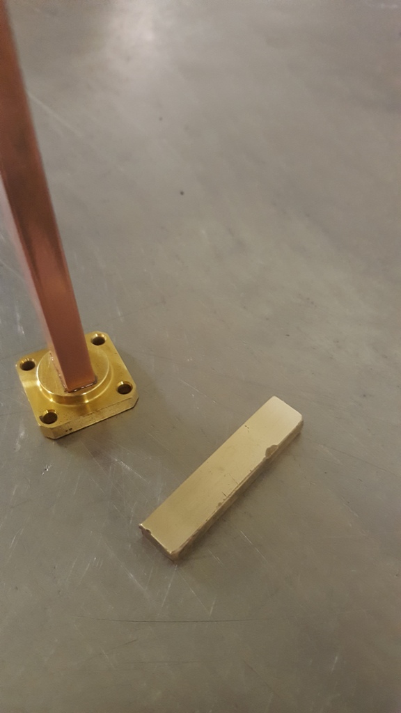
I soldered the guide into the flange using standard solder and a soldering lamp.
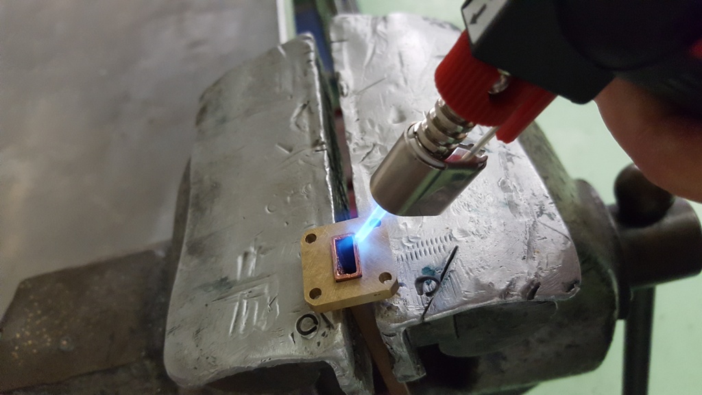
I deliberately let the waveguide protrude a bit from the flange. After soldering, it lookds quite ugly….
… the soldering quality actually looks worse on these pictures than it is. I paid attention that the solder properly melt around the whole waveguide. To ensure that the solder will not only wet the brass, I grinded the copper waveguide a bit using sand paper.
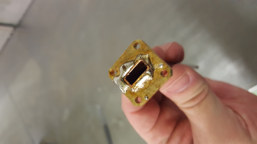
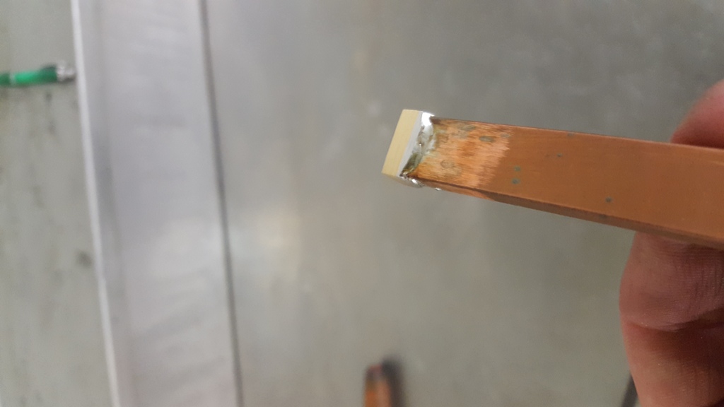
Now it comes to the time to grind of the excess solder and waveguide piece protruding! On this picture one can actually see that the solder indeed made a good connection to the copper.
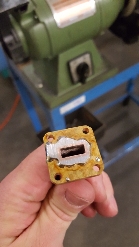
After further grinding….

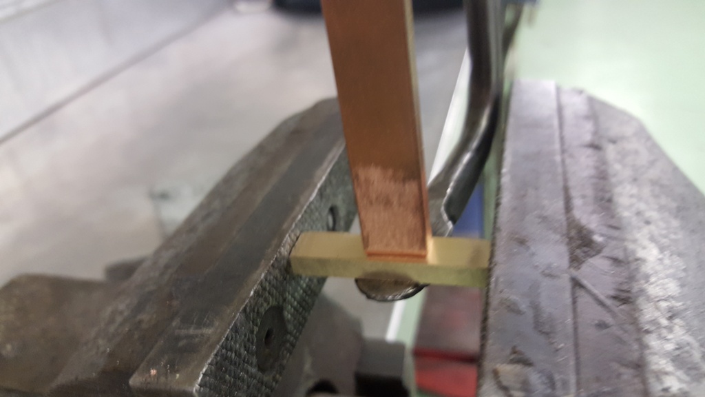
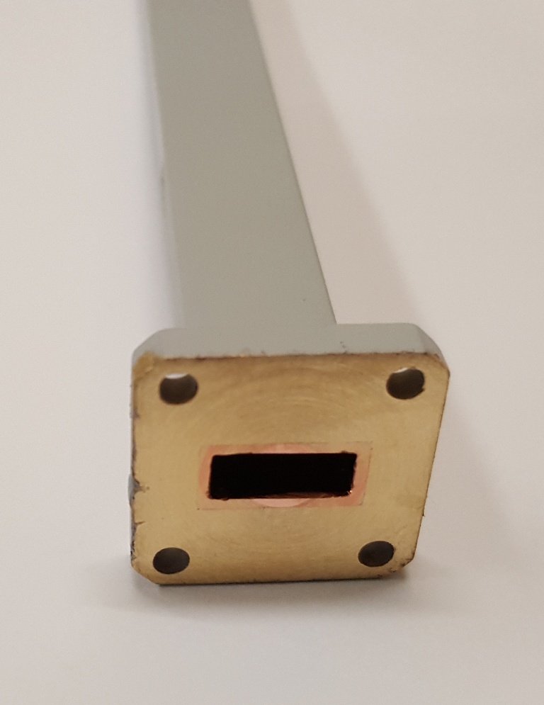
Now I have at lease a nice flange and a piece of open waveguide. To make a waveguide termination, the guide needs to be closed at the end and filled with an absorbing material. For this, I will try to solder a small piece of brass to the end of the guide, as seen below:

After grinding off excess brass:
Now comes the interesting part. Filling of the guide with absorbing material! For this purpose, I got a box with some remainders of carbonyl iron powder from work. There we use these to make microwave absorbers up to the THz range. I will mix the carbonyl powder with some epoxy. All I have is this epoxy called Multicast.
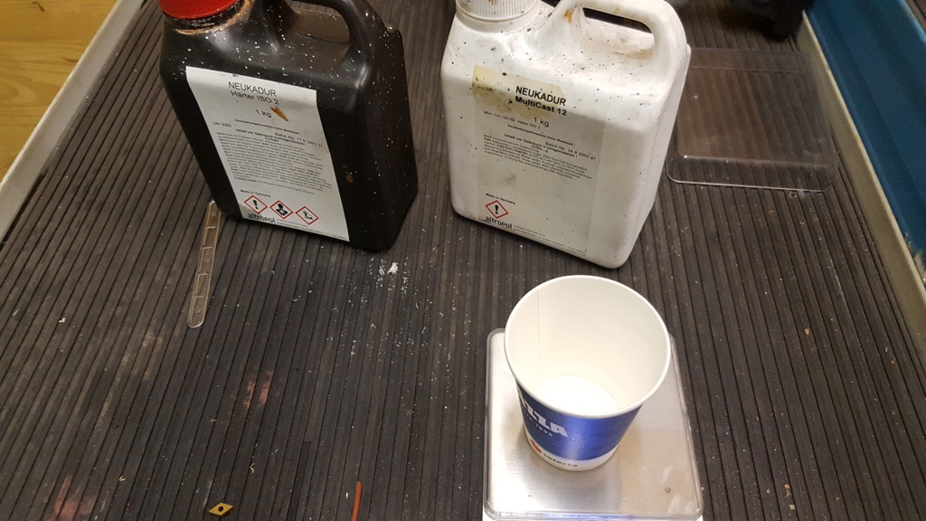
After mixing hardener and resin 1:1, the mixture becomes quite hot and within few minutes it already becomes quite hard, so everything has to be prepared well before mixing the components! I use the tip of a knife to put some carbonyl into the epoxy mixture.


Because the powder is so fine it needs quite a bit of stirring to mix the components well.
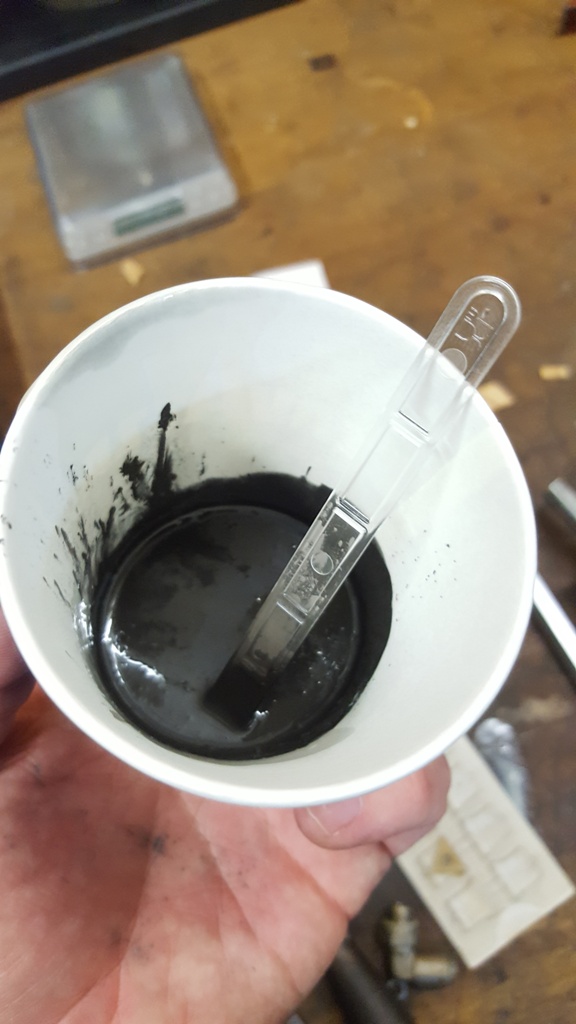
Fun fact: as long as the epoxy is liquid, this mixture behaves very similarly to a ferrofluid, because the carbonyl powder is magnetic, the liquid can be pulled around with a magnet 🙂
Anyway, I had my previously soldered waveguide in the vice, and poured the epoxy/carbonyl mixture into the waveguide, making sure that no droplets go onto the flange.
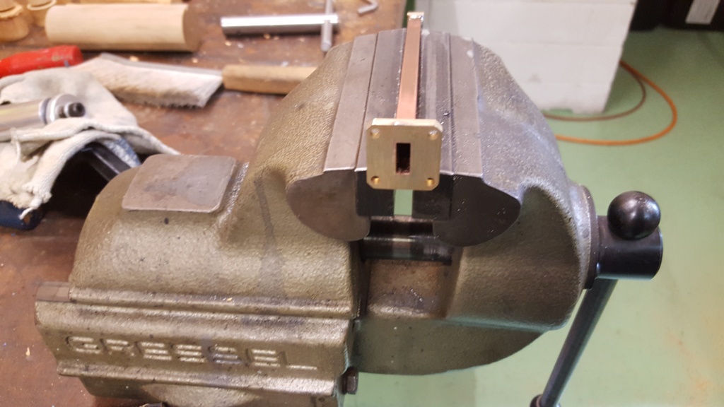
The waveguide is not horizontally within the vice, but at an angle of a few degrees, such that the epoxy is not perpendicular to the wwaveguide walls but more like a wedge. Since it hardens so fast, one must hurry a bit when pouring the epoxy into the guide, otherwise it will not form a proper wedge. I hope I was fast enough. I have a small endoscope camera, but it is not small enough to look into the guide and check whether it is filled properly, but lets hope 😉 At work I will for sure have a minute to connect the termination to a network analyzer and measure. My own NWA only goes to 6GHz, I am still looking for a HP 8510…
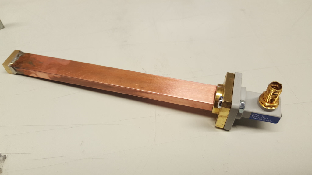
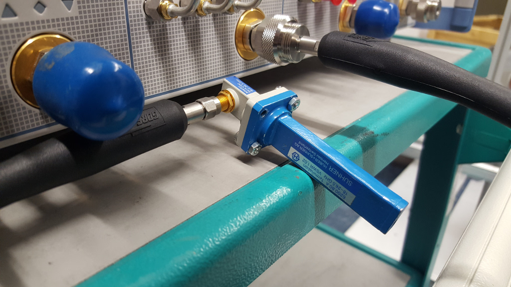
So I used the R&S ZVA40 at work to measure the return loss of my termination and compare it to a commercial termination from Huber+Suhner. This is my termination, connected to a Huber+Suhner waveguide to coax adaptor:
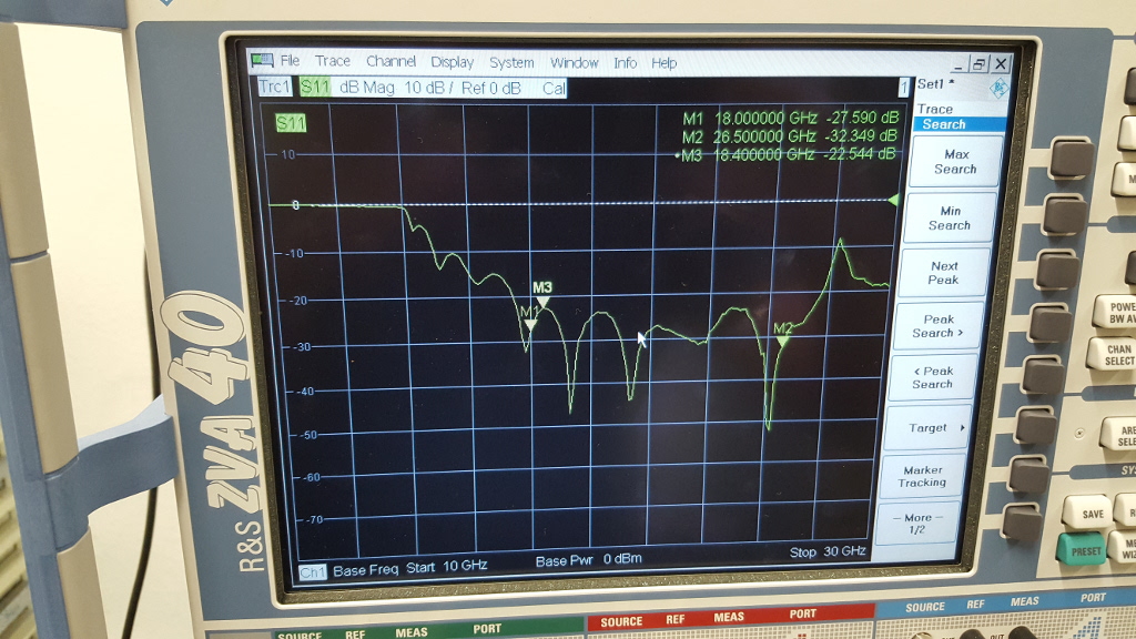
Test setup with the ZVA40:
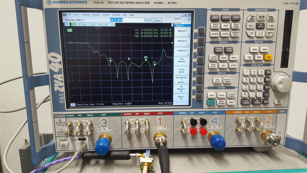
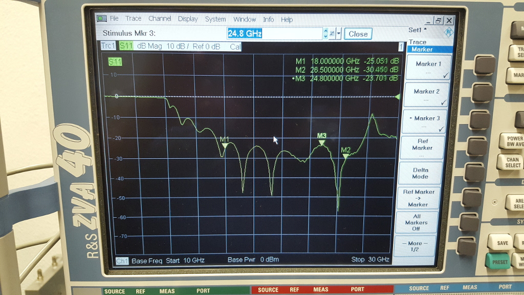
The markers 1 and 2 show the K band corner frequencies, 18 GHz and 26.5 GHz, respectively, where marker 3 is at the point where the return loss has its worst value, -23.7dB:
Now we compare this measurement to a commercial termination from Huber+Suhner.
The red-ish line is the Huber+Suhner termination, whereas the blue one is my homemade one.
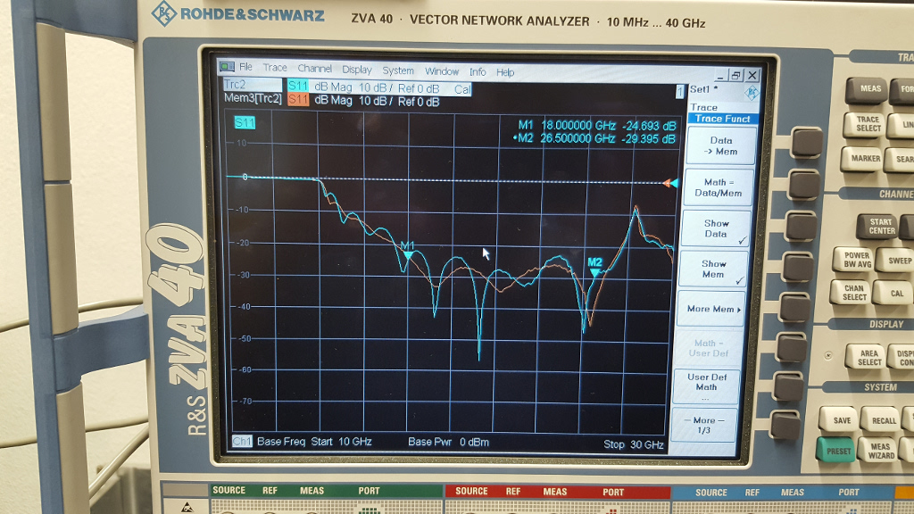
Apparently, the commercial termination is generally flatter, but surprisingly, it is only about 3 to 5dB better than my own termination. Not too bad for my first attempt!
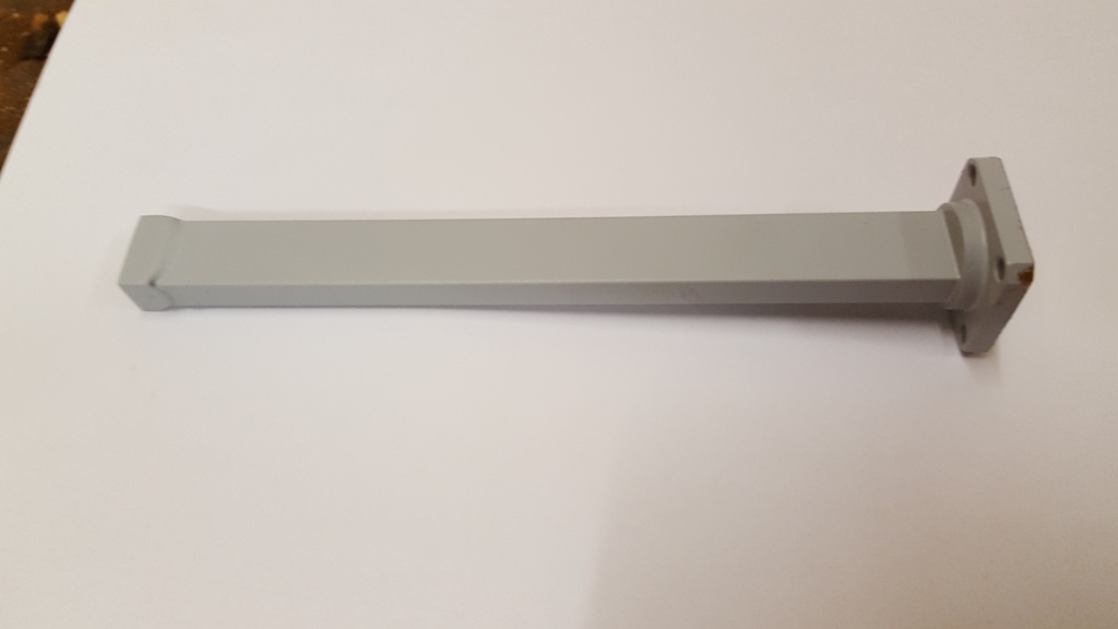
Later I tried to improve the flatness of the flange. It was not terribly good because I grinded it manually… so I used the round piece at the read of the flange to mount the whole thing in a lathe and turned the surface of the flange until it was perfectly flat. Afterwards, I painted the whole waveguide so it looks more professional 😉
I measured the return loss again to see whether it has changed due to the improved surface of the flange. I would say it is a tiny tiny bit better now 🙂
I am not sure how much power this termination can take, but since there is quite a lot of dissipative material within the waveguide, I would assume it can easily take a few watts. Unfortunately I have no possibility to test that, my best signal generator produces only about 5..10 mW at this frequency range… I was always bad in thermodynamics, but I’ll give it a try: the mass of the epoxy inside the waveguide is roughly \( m \approx 5\,\mathrm{g} \). I have no data about the heat capacity, so I just take the heat capacity of some other epoxy I found, which is \( C = 1.4\,\mathrm{\frac{kJ}{kg\cdot K}} \). We can allow for a maximum temperature difference of, say, \( 50\,\mathrm{K} \). So the heat quantity is around \( \Delta{}Q = C\cdot m \cdot \Delta{}T \), which amounts to \( 350\,\mathrm{J} \). This is equal to…
- 350 W for 1 second
- 35 W for 10 seconds
- 3.5 W for 100 seconds
- probably 3.5 W or so forever, since at some point this thing will reach an equilibrium point. This is quite nice, because the commercial termination I used is rated for 1 W.
The next thing to make is a waveguide directional coupler. Together with this load it woud allow to measure S11 with a power meter and a signal generator, almost like a scalar network analyzer!