I was working quite a while on my GPSDO project. This post is still work in progress and I will provide some updates from time to time 😉
I have already made an antenna for the GPSDO and tested it with a NEO6 module from uBlox. Apparently, the antenna seems to work fine, so I started to design the hardware around a LEA-M8T GPS module which is a real GPS timing module.
The schematics, PCB prints and assembly drawings can be found in the attachments section below.
Features of my GPSDO hardware:
- integrated distributor
- 1PPS output
- graphics LCD to display status info
- integrated amplifier
The distributor
I wanted to have multiple 10 MHz outputs. So I decided to add a distributor. It should have following properties:
- sine wave output, 50 Ohms
- low harmonics
- low noise
- outputs should be well de-coupled from each other such that instruments connected to different outputs cannot ‘see’ each other
I found some info about the distributor made by W.J. Wriley, who is the father of the well known Stable32 software. He uses video OpAmps to de-couple the individual outputs, have some gain and a driver for the 50 Ohms output. So I did the same, but I didn’t want to use a split supply. Instead, I use +12V only. The OpAmps are configured asinverting amplifiers. The inverting amplifier configuration has the advantage that it precisely allows to design it for a specified input impedance. Since my OCXO is designed for a load of 50 Ohms, I used 4 of those inverting amplifiers in parallel, with around 200 Ohms input impedance each. So the OCXO sees a resistive 50 Ohms load.
Shown below is the schematic of a single amplifier.
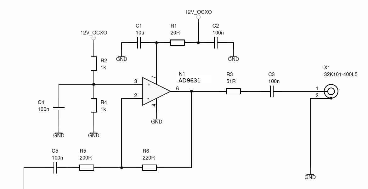
From an AC point of view, pin 2 of the OpAmp is grounded, so at the input of R5, one sees 200 Ohms. This is confirmed by means of a LtSpice simulation.
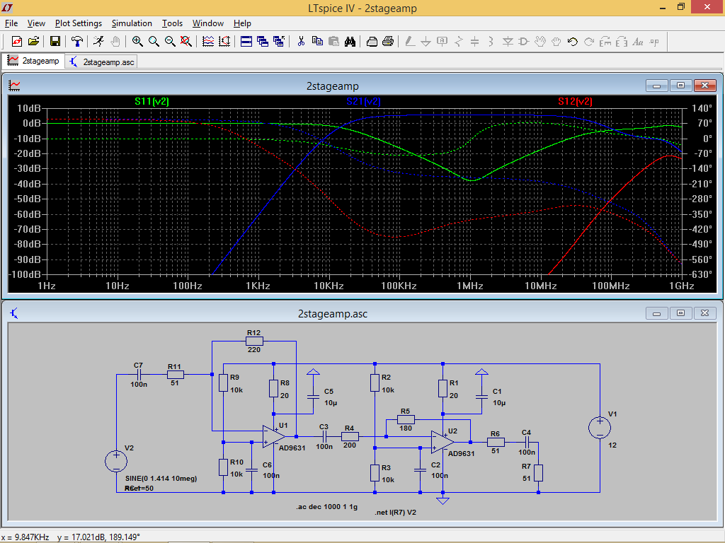
Shown below is a LtSpice simulation which confirms that….
- the input impedance of the amplifier at 10MHz is good enough for a return loss of around -20dB, therefore, the input impedance is basically equal to R11;
- the forward gain S21 is in this case \( \left| S21 \right| = \frac{R_{12}}{R_{11}} \cdot \frac{R_{5}}{R_{4}} \)
- According to the Simulation, the reverse Isolation is incredibly high, namely around 140 dB. I don’t believe this very value, but I am happy if the reverse Isolation is around, say, 30 dB or so. We require a high reverse Isolation to prevent that the OCXO can “see” what different loads are connected. And, further, if one has connected a not-so-good Instrument which produces some ‘dirt’ at its 10MHz output, this is isolated from other instruments.
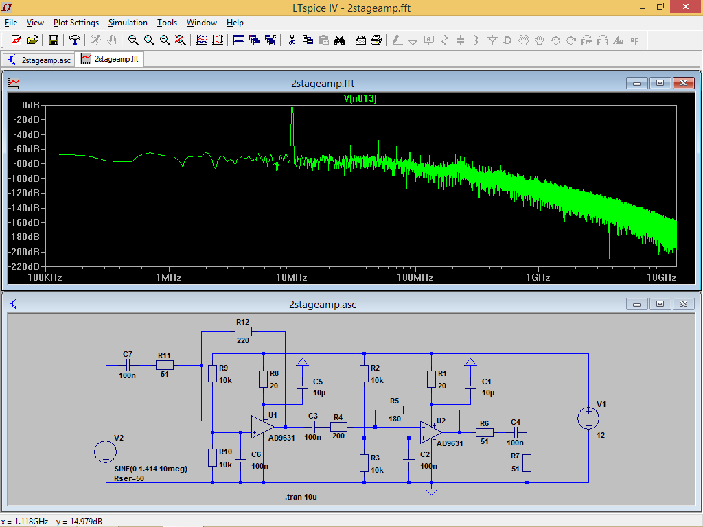
I also checked whether the OpAmp produces some harmonics in this configuration. According to the simulation, there should be not much around, probably 20 MHz and 30 MHz, but both around 30 dB down. Good enough! I don’t think it is necessary to add an extra lowpass filter to clean up the harmonics.
The power supply
Nothing special. I use a wall wart 15VDC power supply. On my board, I have a 7812 for the analog parts (OCXO, distributor) and a switching regulator for the MCU.
I didn’t want to put too much effort into building a power supply 🙂
MCU part, 1PPS output etc
I use a STM32F303K6T6 microcontroller to steer the OCXO, read NMEA data from the GPS module and display some info on the graphics LCD.
The MCU is clocked by the OCXO. The CPU clock drives a counter, and the 1PPS signal from the GPS module drives a capture input. On every rising edge of the 1PPS signal, the counter’s current value is captured while the counter is kept running. By comparing the current and the previous capture values, the OCXO’s frequency can be determined. Since the counter is never stopped, at some time, every slight frequency error can be detected – even if the OCXO is off by, say, 1mHz. This will need a measurement time of 1000s, though.
The MCU has also an output to a 74HC541 which is used as a driver.
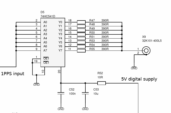
I paralleled all 8 outputs of the driver with resistors. The 1PPS output thus has an impedance of roughly 50 Ohms and provides a 5V signal. A timer in the MCU will be used to generate an accurate 1PPS signal.
A EA-DOGM128 graphics display is connected to the MCU to display status messages.
GPS module and OCXO
The GPS module LEA-M8T is used. Only its UART, 1PPS output and the RESET signal are routed to the MCU; other pins are unused.
A MMIC GALI-S66+ is used as preamplifier.
The OCXO used is an AXTAL AXIOM75-11 which is specified for ultra low phase noise. Phase noise is critical in my design since I would like to use thhis GPSDO as reference for my spectrum analyzers – the HP 8568B and 8566B S/As require a reference oscillator with -140dBc @ 100Hz phase noise or better. My OCXO was measured by AXTAL and according to the measurement report, its phase noise is around -155dBc @ 100Hz. Awesome!
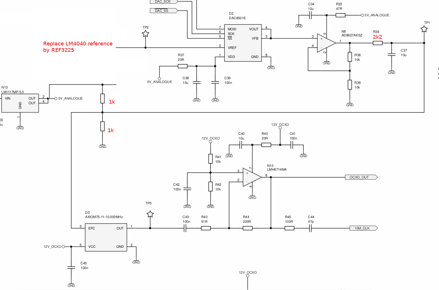
A DAC8501 16Bit DAC is used for the steering of the OCXO’s EFC input. The DAC uses a reference voltage of 2.5V and a noninverting amplifier with a gain of 2 is used to increase the DAC’s output swing to 5V. A RC lowpass filter with R=1k and C=10uF is used at the EFC input to protect it from any spikes or noise and to reduce the slew rate of the EFC signal.
The PCBs and completely assembled unit
This is how my unit looks from the exterior:
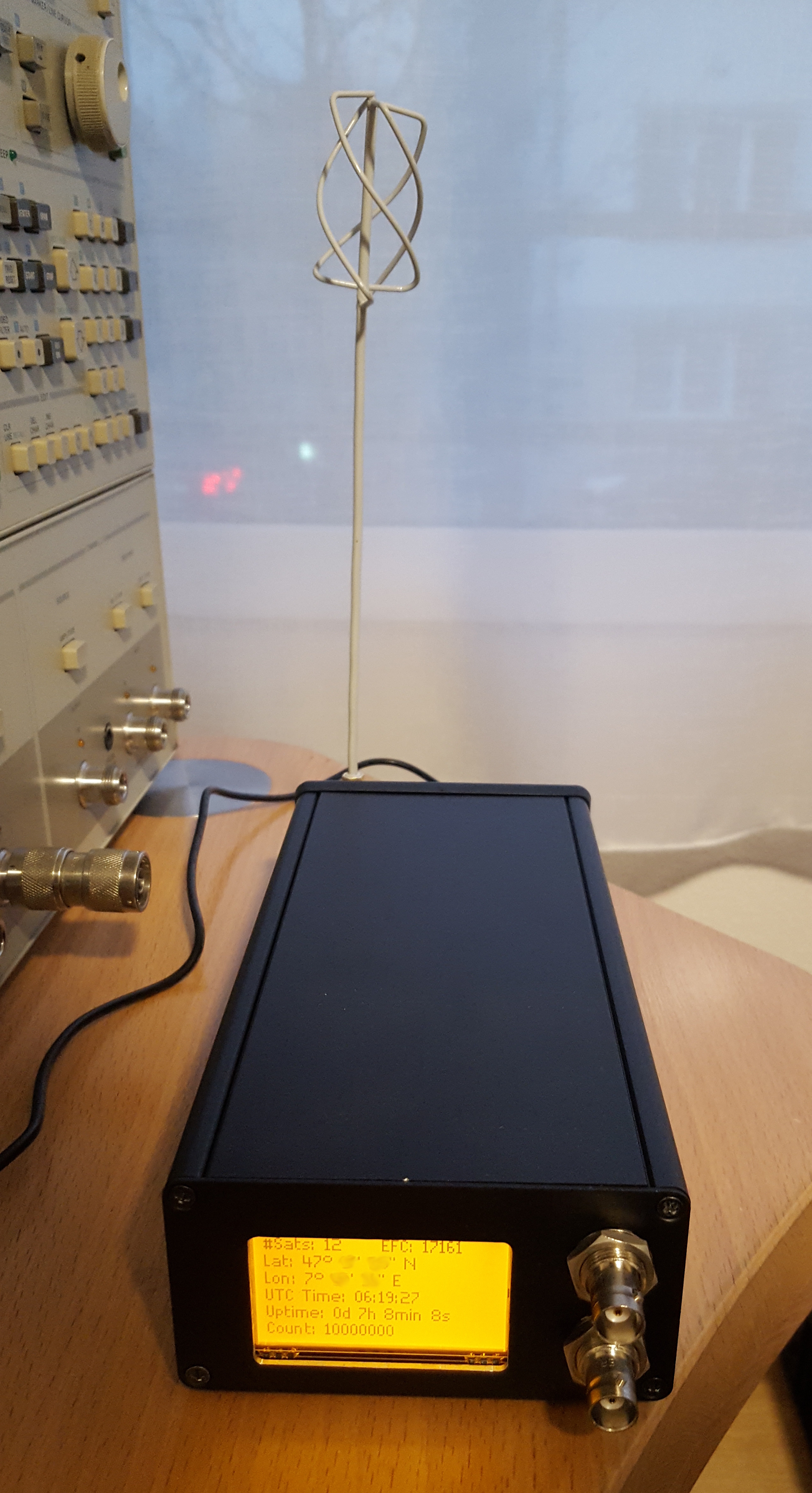
The position next to my HP collection of measurement equipment is far from ideal, but good enough for now, since the GPS module sees 12 sats anyway. But later, an active antenna outside would be better.
From the inside, it looks as follows:
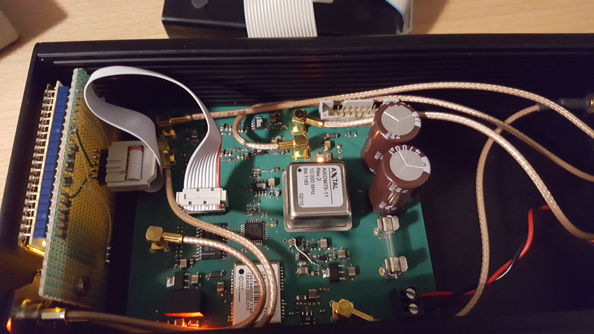
I have used some MCX connectors to connect the front and rear pabel BNC adapters to the PCB.
Some pitfalls…
While I was doing my first experiments with my GPSDO hardware, I found several problems.
Unstable PLL
I used the PLL of the microcontroller to boost the CPU clock and the clock for the timers/counters to 50MHz. This would also increase the resolution of the measurements, so I thought at least! but I was wrong.
The PLL of the STM32F303 has a specified jitter of around 300ps…
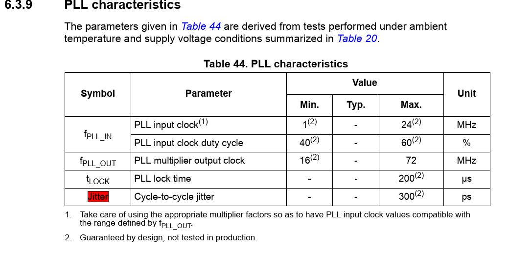
… which would be fine for this application. But, what the datasheet doesn’t tell, is that the PLL is quite unstable in frequency and is somewhat FM modulated – there is a cleraly visible sawtooth-shaped frequency variation, as discussed here! So the PLL is basically useless for this kind of application. I had to drop the idea of increasing the resolution with the aid of the PLL 🙁
Too unstable reference voltage
I further noticed that my DAC had a slight temperature drift. I didn’t think about the temperature coefficient of the LM4040 I used as reference voltage for the DAC, so I needed to replace the reference by something more stable. I had some REF3225 at hand, which are way better. Unfortunately, not the same package, so some slight rework was required 🙂
With the new reference, stability has increased.
Too wide tuning range
With my initial schematic, the DAC can provide a tuning voltage of 0 to 5 Volts for the EFC signal. According to the datasheet…
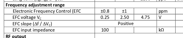
… this would allow the OCXO to be pulled by +/-10 Hz. More than enough for the whole lifetime of the OCXO, including some aging, but too much for precise adjustment! So I needed to add some additional resistors to the DAC circuit to lower the tuning range.
Now, with the improved EFC circuit, the DAC can produce an EFC voltage in the range from 2 to 3 Volts. This can pull the OCXO barely by 1 Hz in both directions, so it should be fine for now.
Shown below is an excerpt of the relevant part of the schematics where I have added the changes in red.
OCXO temperature dependence
Once the above problems had been fixed, I let the unit run for a couple of days and measured the time interval between the 1PPS of my unit and that one of a Trimble Thunderbolt. Initially, the both 1PPS pulses were around 263ms apart from each other, but otherwise more or less stable. However, when I touched the OCXO, one could clearly see that the time difference began to increase, I assume this was because the OCXO drifted a bit due to a temperature ‘shock’. So I made a little box of styropor (which we actually call Sagex in Switzerland), this is how my box looks like:
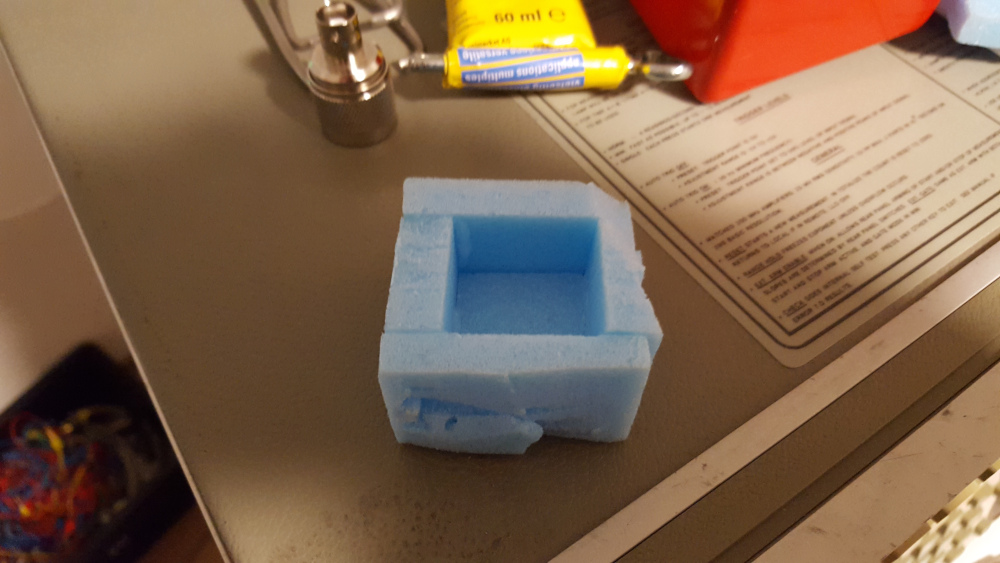
The box looks ugly because I had to cut bits of the walls away such that the box fits beneath the capacitors and the connectors. OCXO with Sagex box on top:
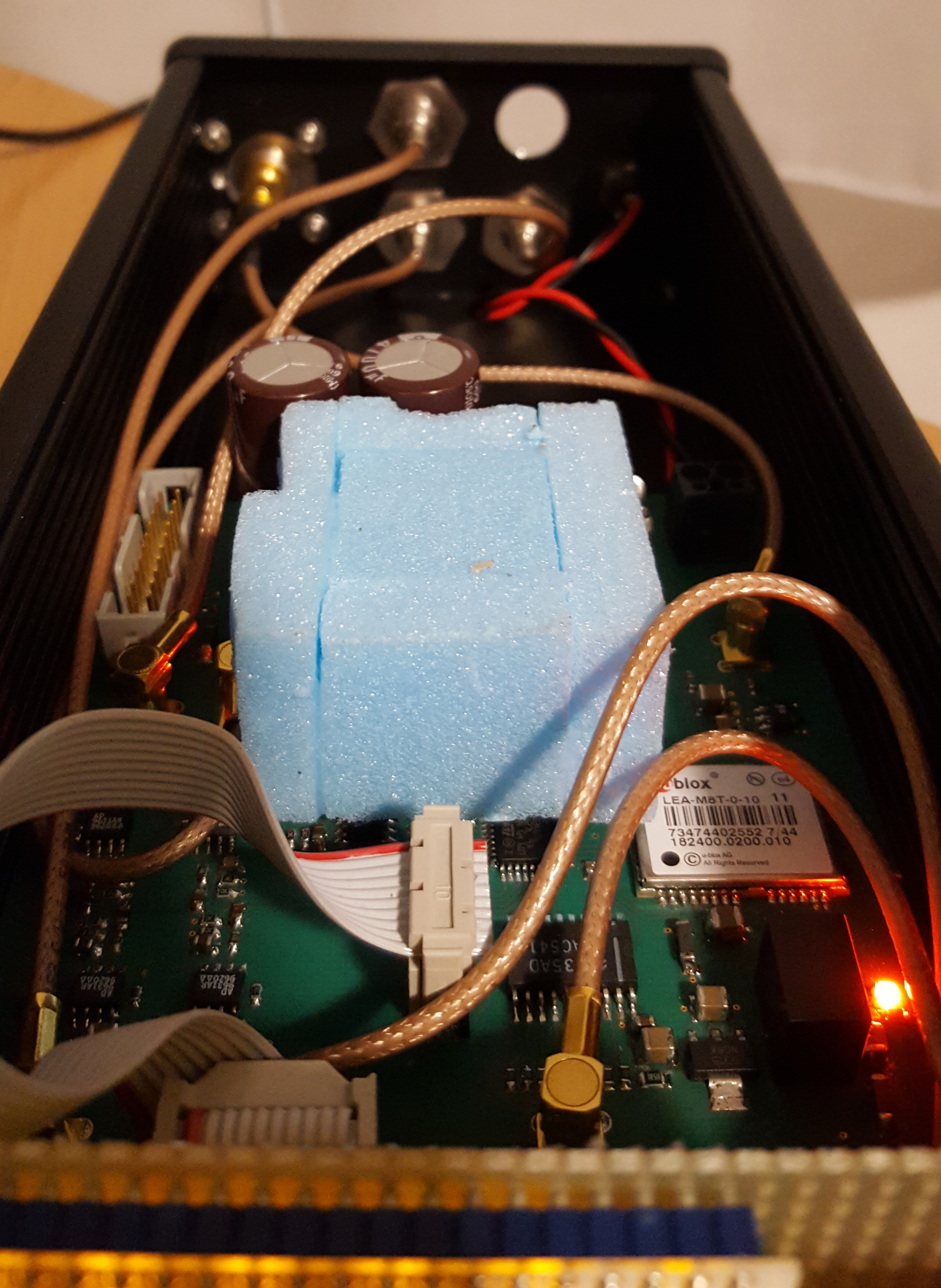
NO this are not gaps in the walls of the box, I just didn’t cut it very nice. The gaps are filled with glue such that any air flow or so is prevented.
Actually, I was already worrying about the temperature stability from the beginning on, because my OCXO is, as fas as I know, not a double oven type, but a single oven. Perhaps I will make some day a double oven adaptor (mounting the OCXO in a little metal box with even more Sagex and an additional heater).
Software
Software consists of following modules:
- NMEA parser to read position, time and other stuff from the GPS module
- graphics LCD driver including font generator
- a state machine which controls initialisation of hardware, discipline and holdover mode
The NMEA module.
This module provides the function
nmea_t nmea_parse(const char* str, nmeadata_t* output);
which parses a NMEA sentence. The different types of sentences the parser looks at can be configured via macros. The ckecksum is verified, if there is one, and the NMEA data is returned in the union nmeadata_t. The function returns the type of NMEA sentence.
The LCD module.
I got the code from a friend and modified it a bit. Altough not used in the GPSDO, I wanted a LCD library as versatile as possible, therefore, things like a Bresenham algorithm for drawing are also included. The library works with different types of displays, since it accesses the hardware onyl via three externally provided functions:
/* initialise the hardware associated with the display and send theinitialisation sequence to the display */
extern void lcd_lowlevel_init(void);
/* send a byte to the display, possibly a command or a data byte */
extern void lcd_lowlevel_sendbyte(bool command, uint8_t byte);
/* select or deselect the display (CSB pin) */
extern void lcd_lowlevel_select(bool select);
I have tested the module with two different displays and both worked fine.
Functions provided include:
- clearing the display
- drawing individual pixels
- drawing lines using Bresenham
- drawing strings (similar to
putsorprintffromstdio.h)
A font library with three different proportional fonts (small, regular, large bold) is also included.
The GPSDO main state machne
The main functionality of the GPSDO is implemented in the FSM.
It has following states:
- OCXO warmup. This is the state in which the FSM starts. It implements a 10 minutes countdown on the LCD. During this period, the OCXO can warm up and settle. The GPS module is held in reset.
- After warmup, the GPS module is started. As soon as the GPS module delivers valid time and position data, the FSM switches to the normal state.
- In the normal state, the GPS data (Time, # of sats tracked, latitude, longitude and an OCXO frequency estimate) are displayed on the LCD. Further, the EFC function is enabled. More on that later. As soon as the GPS module sees less than 4 sats or tells that the position or time ar invalid, the state changes to the holdover state.
- During holdover state, the PPS pulses are not processed at all and OCXO disciplining does not happen. Instead, the software simply waits until the GPS position and time are valid and then switches back to normal mode.
Tests
Output spectrum:
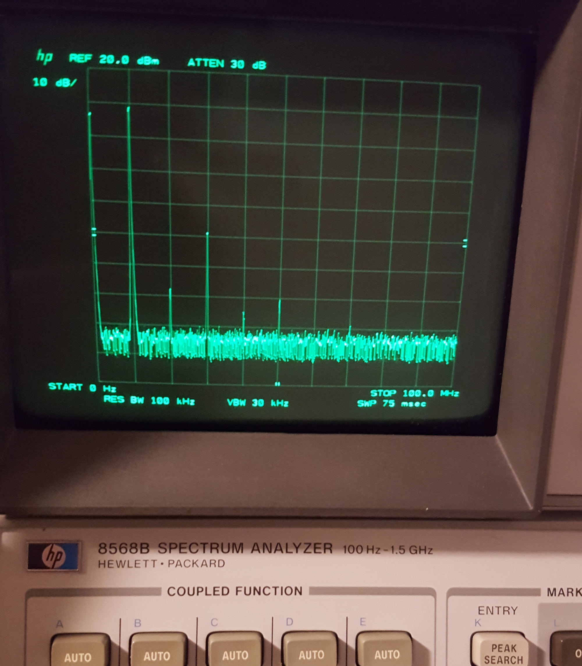
oh dear, it looks like there are some harmonics! well, this was to be expected because even the LtSpice simulation predicted some harmonics. However, they are quite low:
- 20 MHz approx. -55 dBc
- 30 MHz approx. -40 dBc
- 40 MHz approx. -65 dBc
- 50 MHz approx. -60 dBc
The spectrum of the Trimble Thunderbolt looks a bit cleaner, indeed, but I think these harmonics will not be much of a problem.
The 10 MHz itself look as follows…
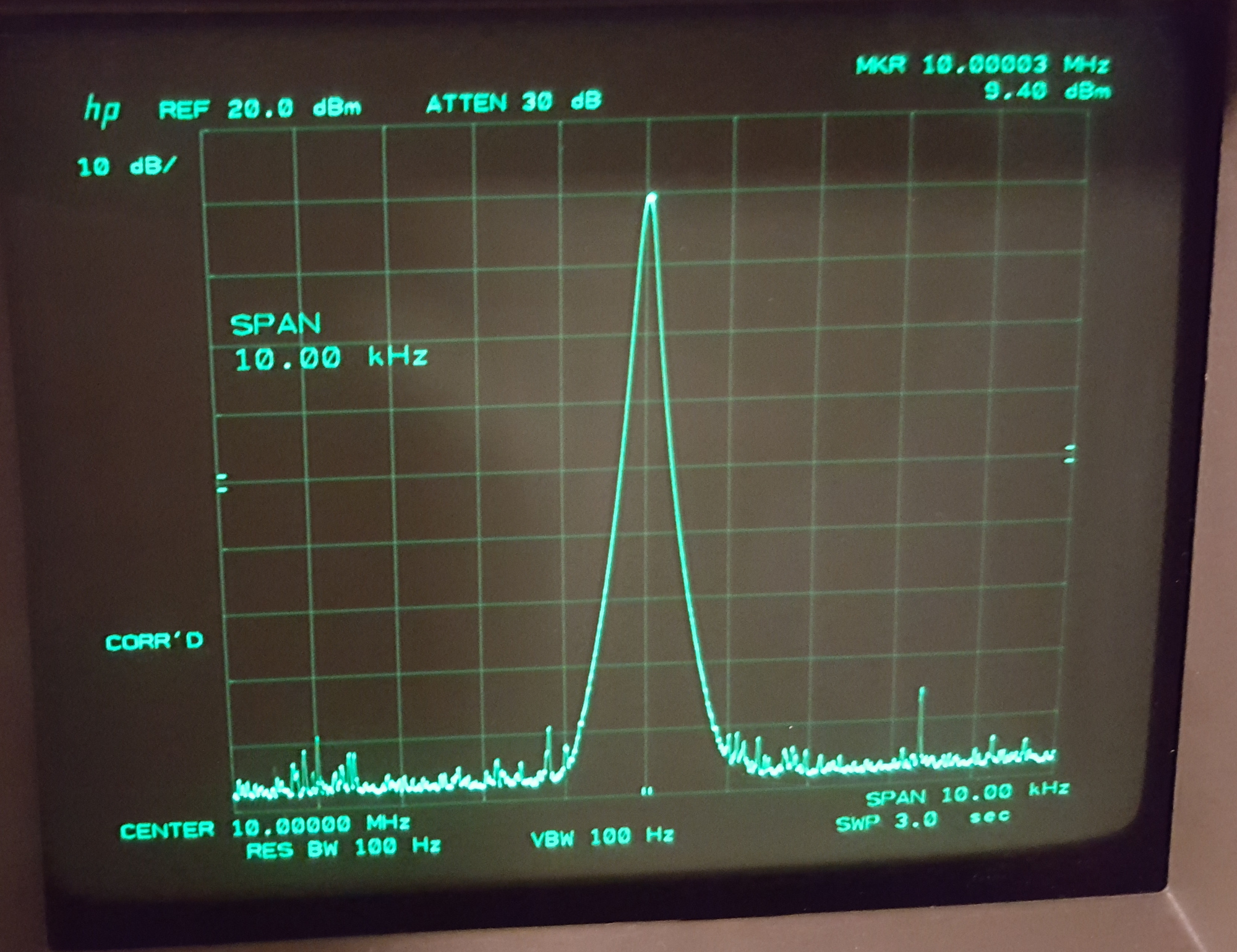
… this screen was taken with my HP 8568B spectrum analyzer, which is a bit noisy, so the phase noise skirts are in reality not THIS bad as it may look. But the power reading is very accurate, 9.4 dBm, this is quite good and agrees well with my 436A power meter with 8481A power sensor.
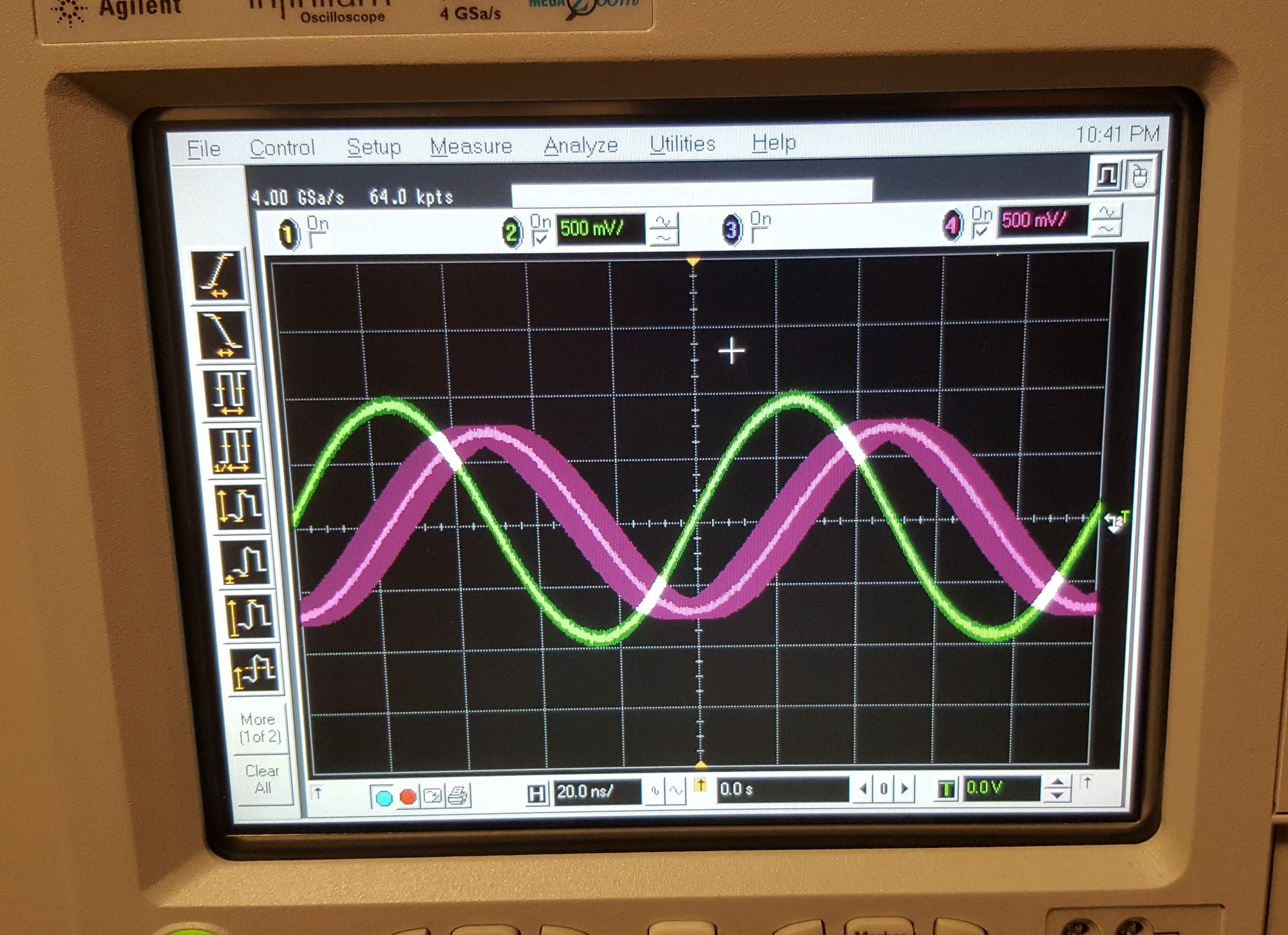
The next test is a long-term measurement where I record both, my own GPSDO as well as the Trimble, on two channels. With my GoPro camera in time lapse mode, I make a screenshot (literally!) every 30sec to see how the phase between the two oscillators drifts forwards and backwards.
I have not yet ready the GoPro video, but this is a scope screenshot using infinite persistence. The green channel is my own GPSDO, whereas pink is the Trimble Thunderbolt. As one can see, within 1 hour, the oscillators drift forwards and backwards a bit, relative to each other. Unfortunately, from this type of measurement it is not possible to determine whether it is the Trimble which drifts or my own GPSDO.
More to come soon!
Resources and stuff
Here is a whole bunch of useful stuff about this topic:
Oscillators, stability and the like:
Über die Stabilität von Oszillatoren und Frequenznormalen
Examples of 1PPS clock measuring systems
Frequency stability measurement: Technologies, Trends, Tricks
NMEA:
GPS NMEA sentence information
Free online NMEA tools
Online NMEA checksum calculator
Hardware:
An octal 10 MHz distribution amplifier
Frequency doubler and 10 MHz distribution amplifier
The use of GPS disciplined oscillators as primary frequency standard
A GPS controller frequency standard
GPS synchronized 10MHz oscillator
Frequenznormal 10MHz
Building a GPSDO controller
The KE0FF GPS disciplined oscillator
Design considerations for optimizing stability in GPSDOs
A GPS-based frequency standard
A simplified GPS derived frequency standard
Lars DIY GPSDO with Arduino and 1ns resolution TIC
